QA Graphics - Experience and Expertise
Johnson Controls Vendor #297586
For over 19 years, QA Graphics has been a trusted partner in providing top-notch graphic design services for Johnson Controls. Our specialized team, based in Ankeny, IA, excels in creating high-quality graphics for JCI’s Metasys User Interface (MUI) platform and Facility Explorer (FX).

QA Graphics is the industry-leading provider of comprehensive BAS graphics services for Johnson Controls Building Solutions, LLC projects. Johnson Controls has named QA Graphics as one of only two pre-qualified subcontractors with the ability to perform graphical work. Our skilled mechanical engineers can create the best system graphics for Metasys UI (MUI), Facility Explorer (FX) and Graphics+. Everything is done in-house, here in the United States, with nothing outsourced overseas.
We’re proud to offer a comprehensive suite of services for SCT (System Configuration Tool) versions 14 through 18, or Metasys revisions 11 through 15. Whether you’re working with an existing standard or looking to set up something entirely new, we’re here to help.
What We Deliver:
Our expertise ensures your system configuration is efficient, visually appealing, and perfectly aligned with your project requirements. Let us help simplify your workflow and elevate your project outcomes.
Get in Touch!
Our Services Include:
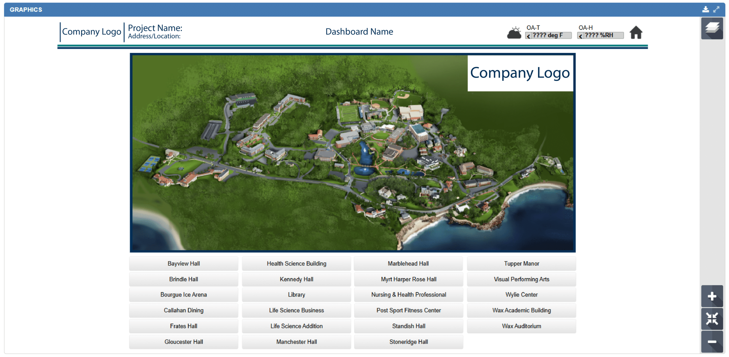
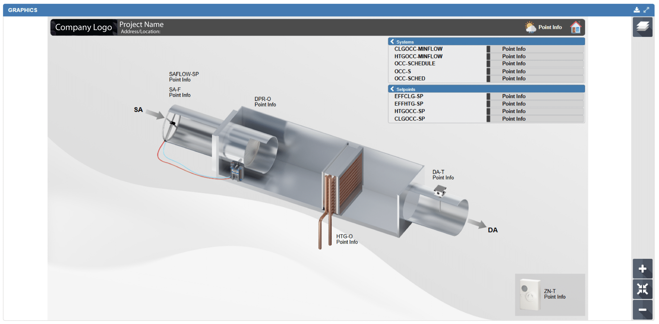
1. SYSTEM GRAPHICS
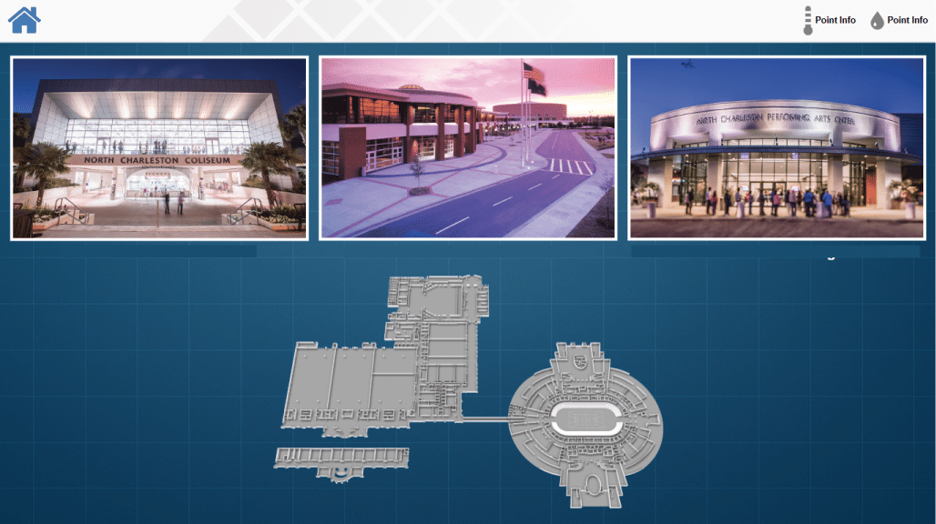
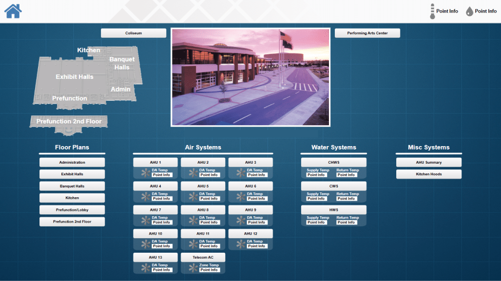
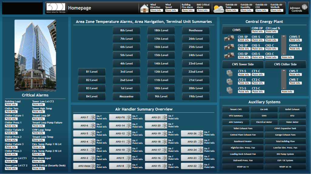
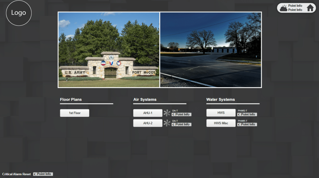
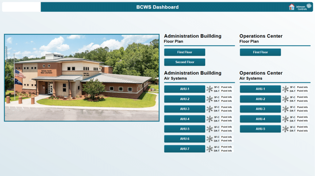
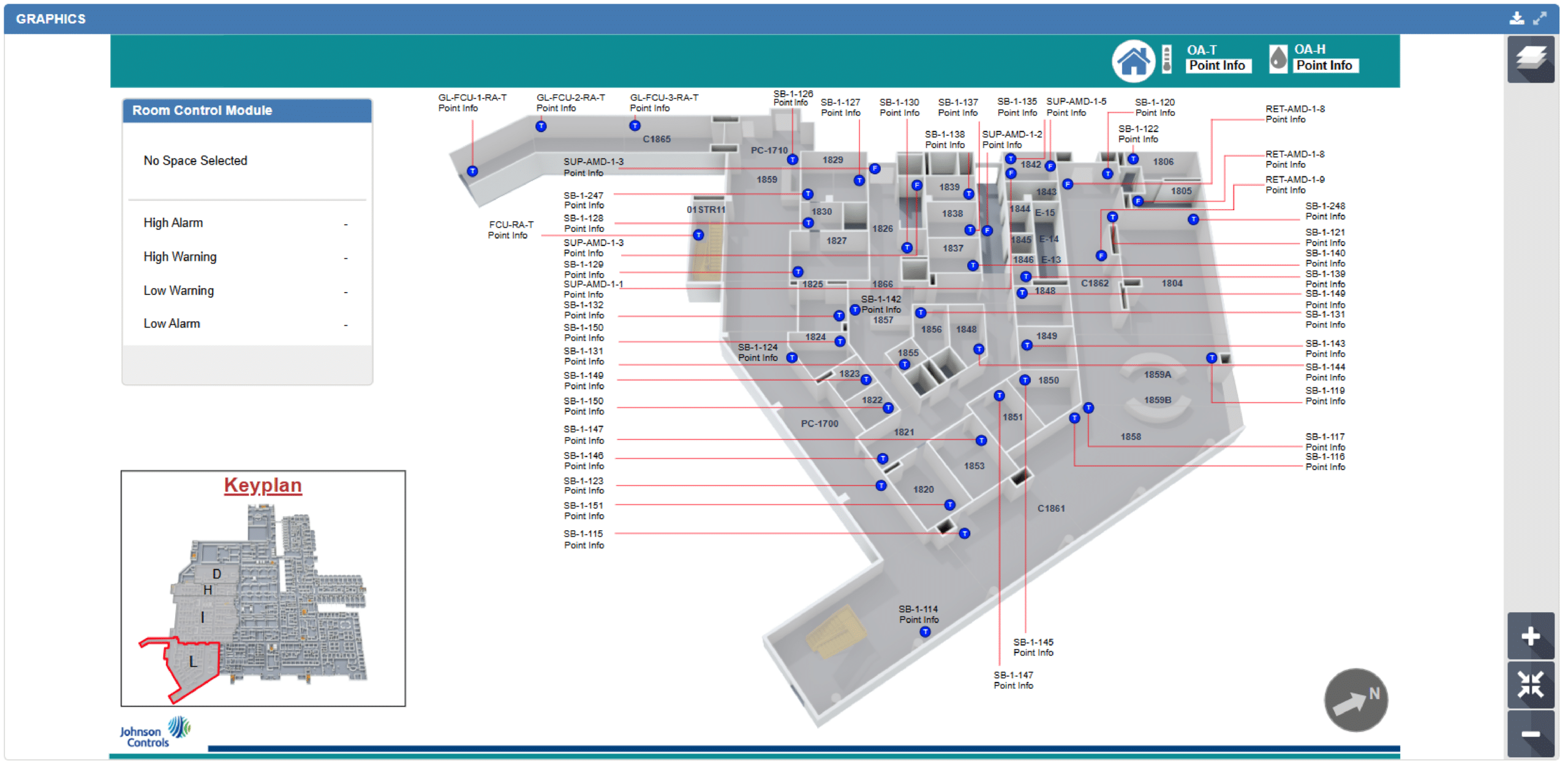
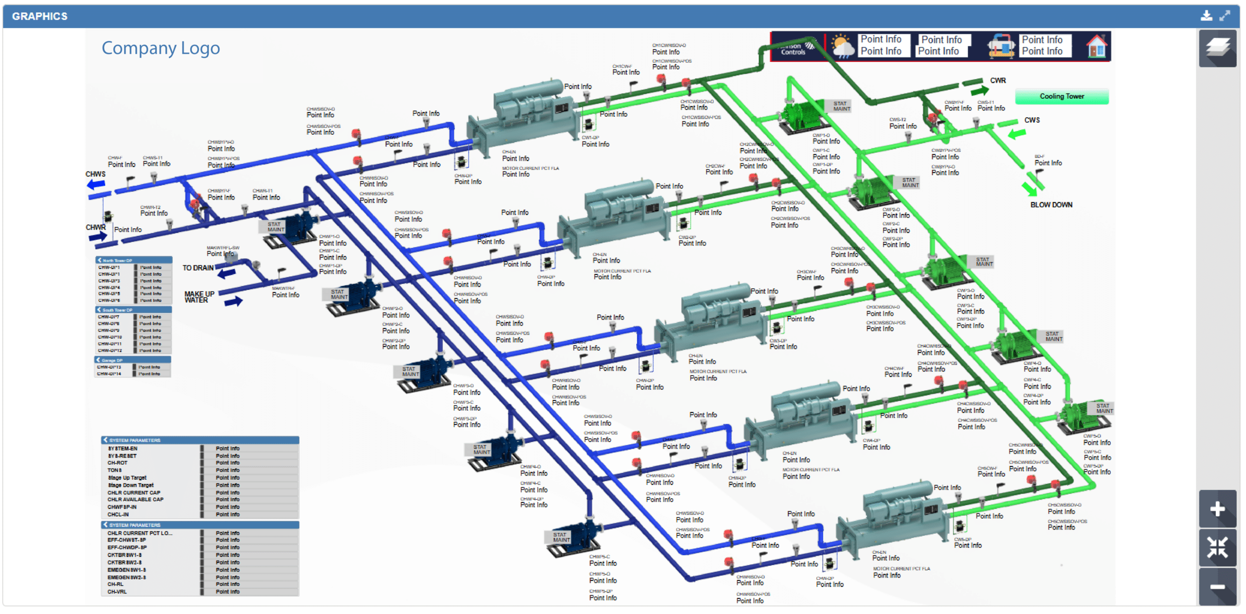
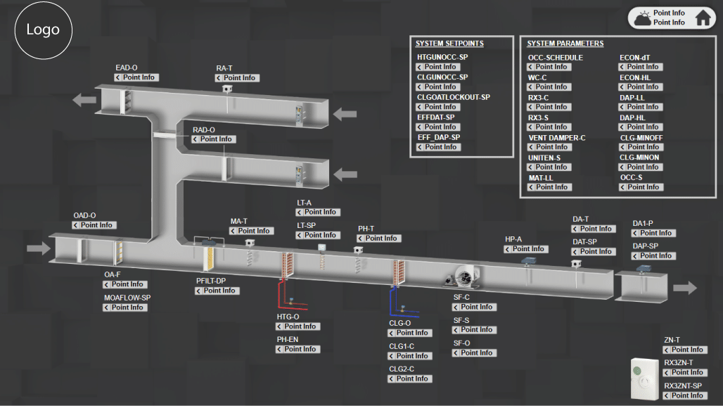
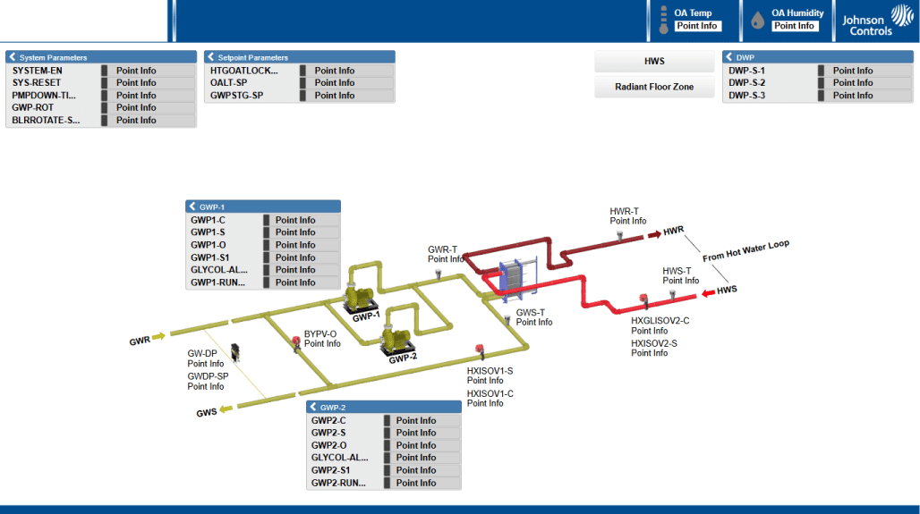
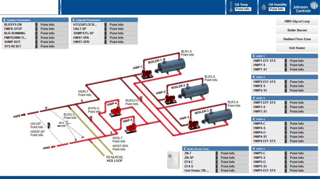
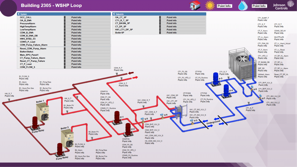
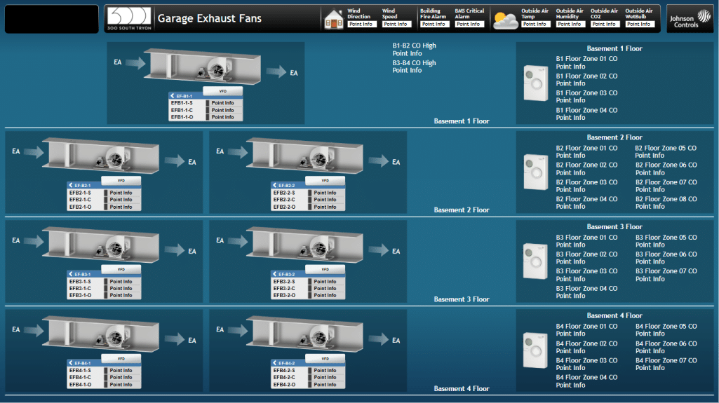
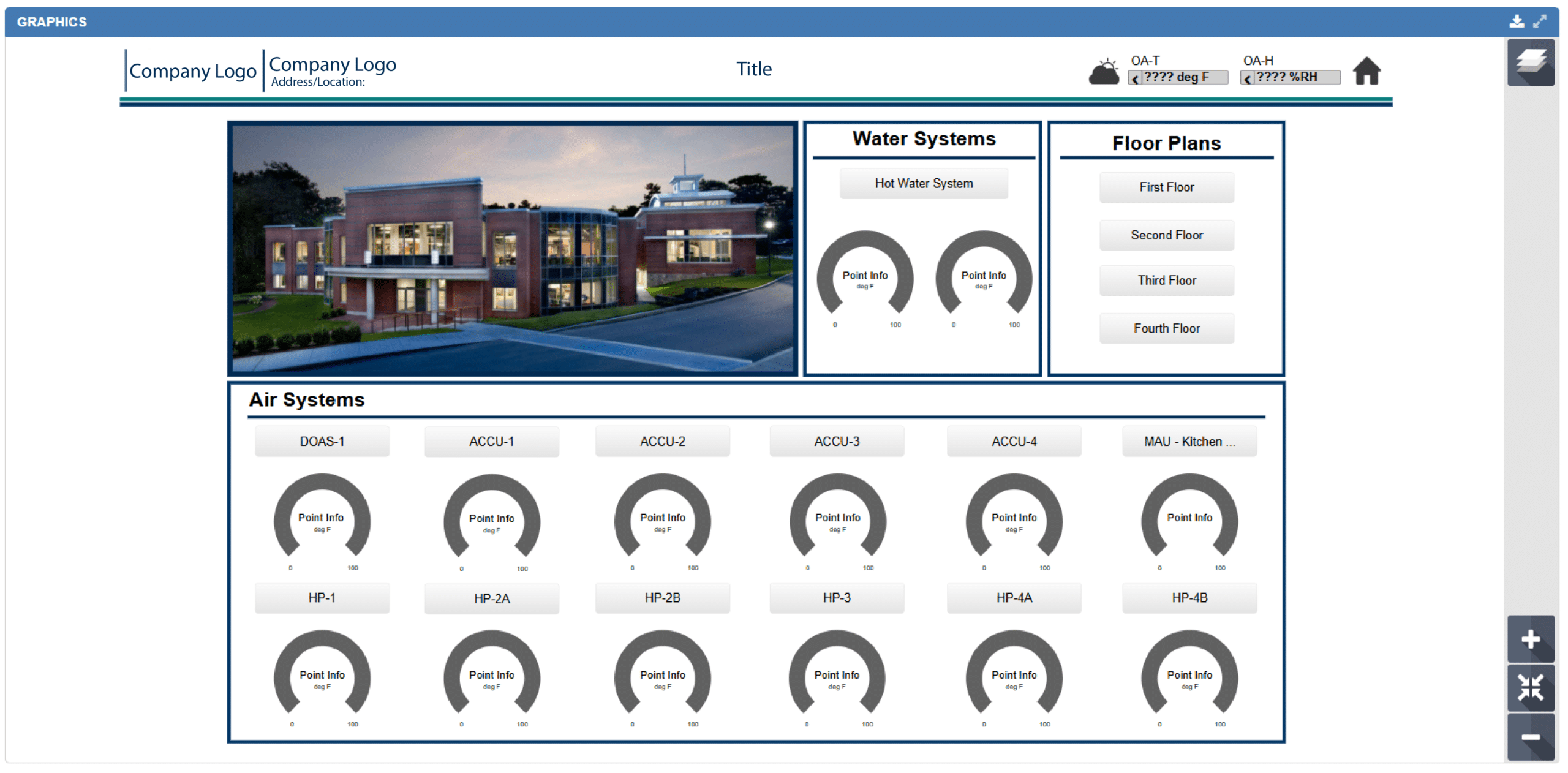
QA Graphics specializes in creating high-performance system graphics for Metasys UI and Facility Explorer (FX), delivering visually engaging and intuitive user experiences across both platforms.
For Metasys UI (MUI), our team is highly experienced in developing custom front-end graphics, including the spaces and definitions that power the interface. Using advanced photo-realistic graphics for equipment, systems, and floor plans, we create clean, consistent designs tailored to each customer’s operational needs. Our collaborative submittal process ensures every project meets project standards, branding requirements, and user expectations.
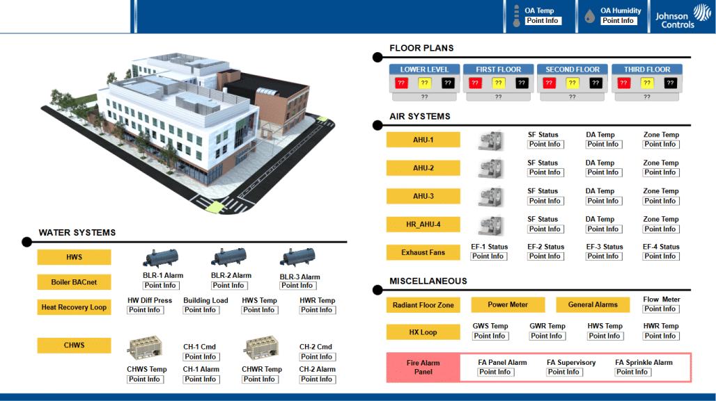
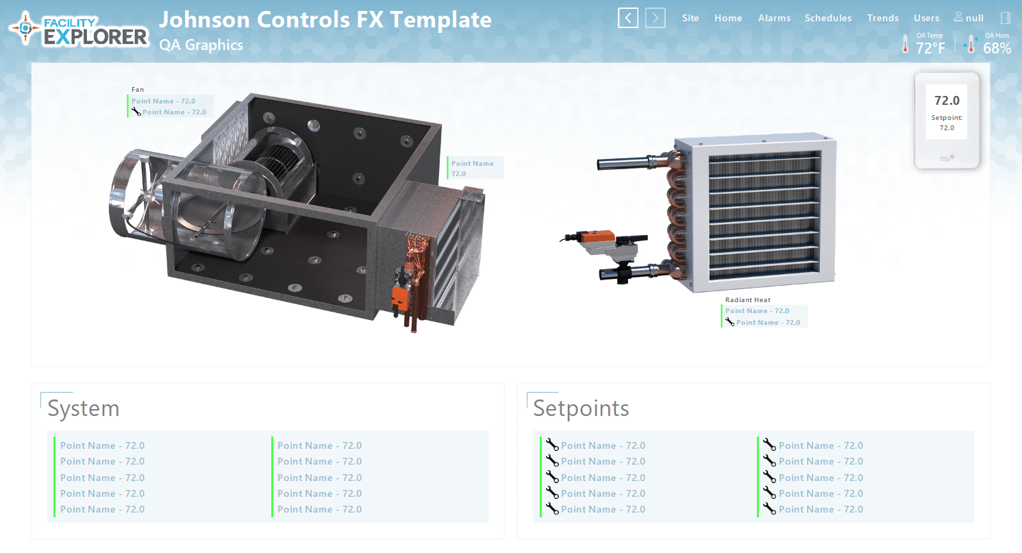
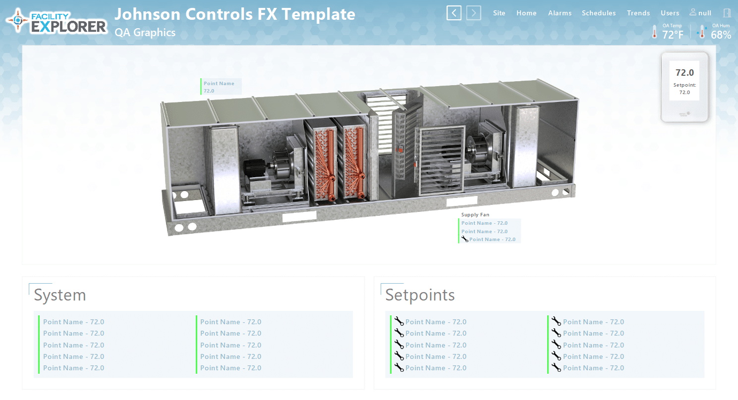
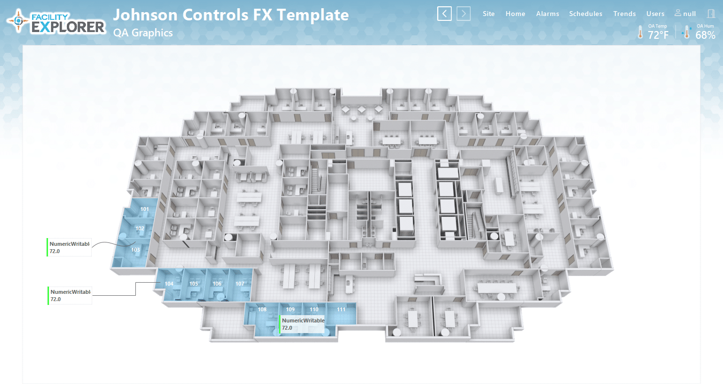
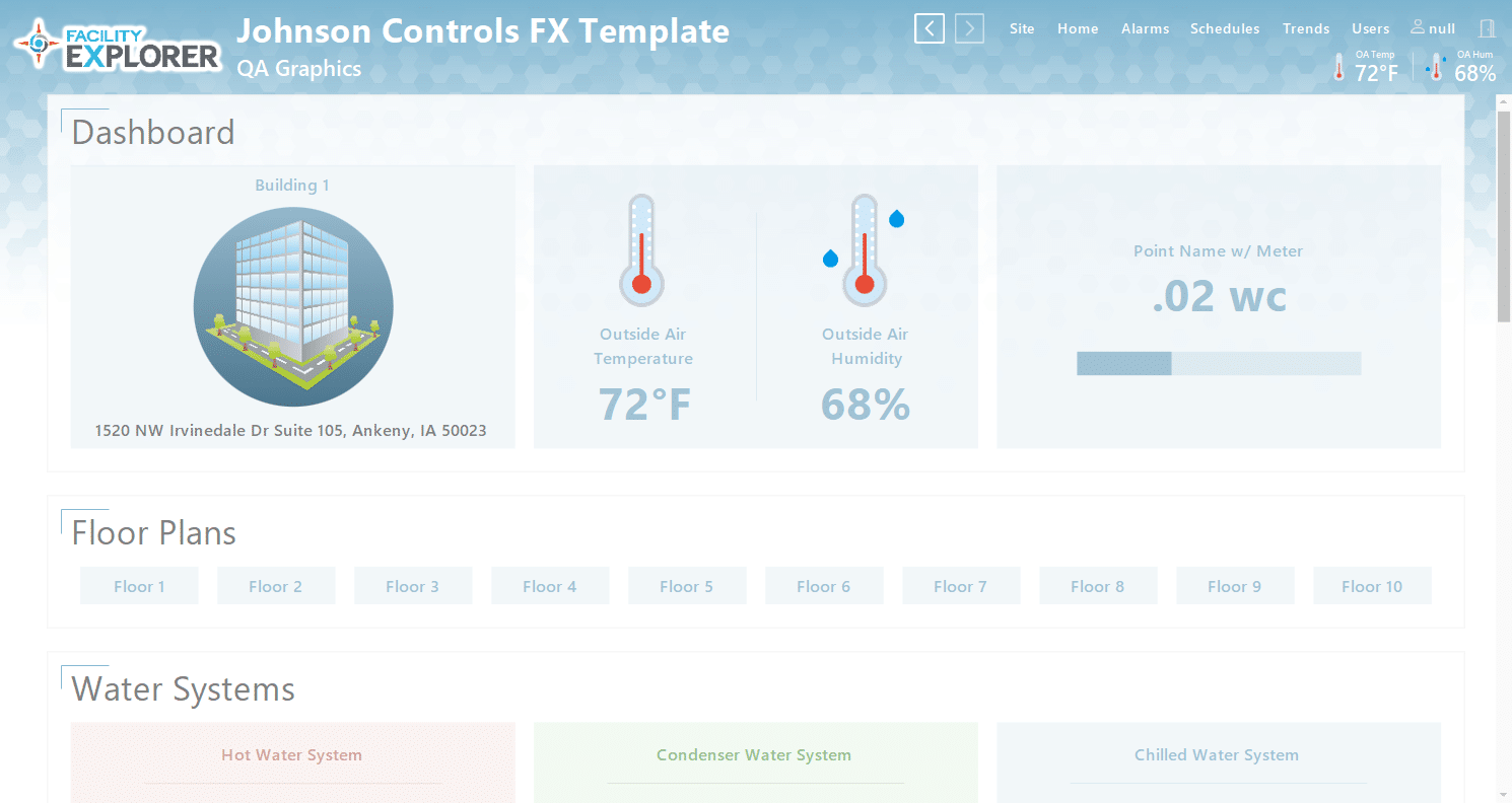
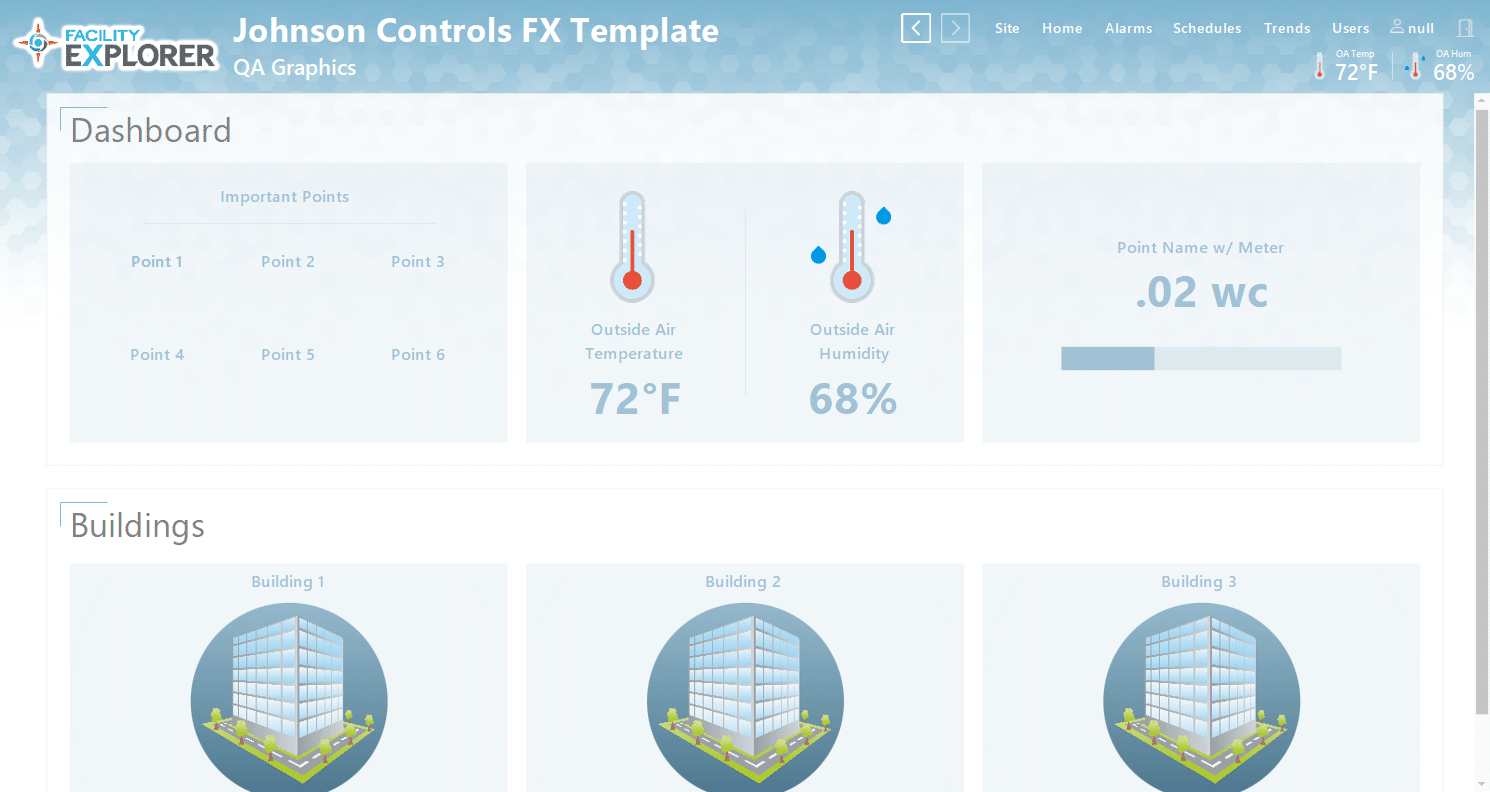
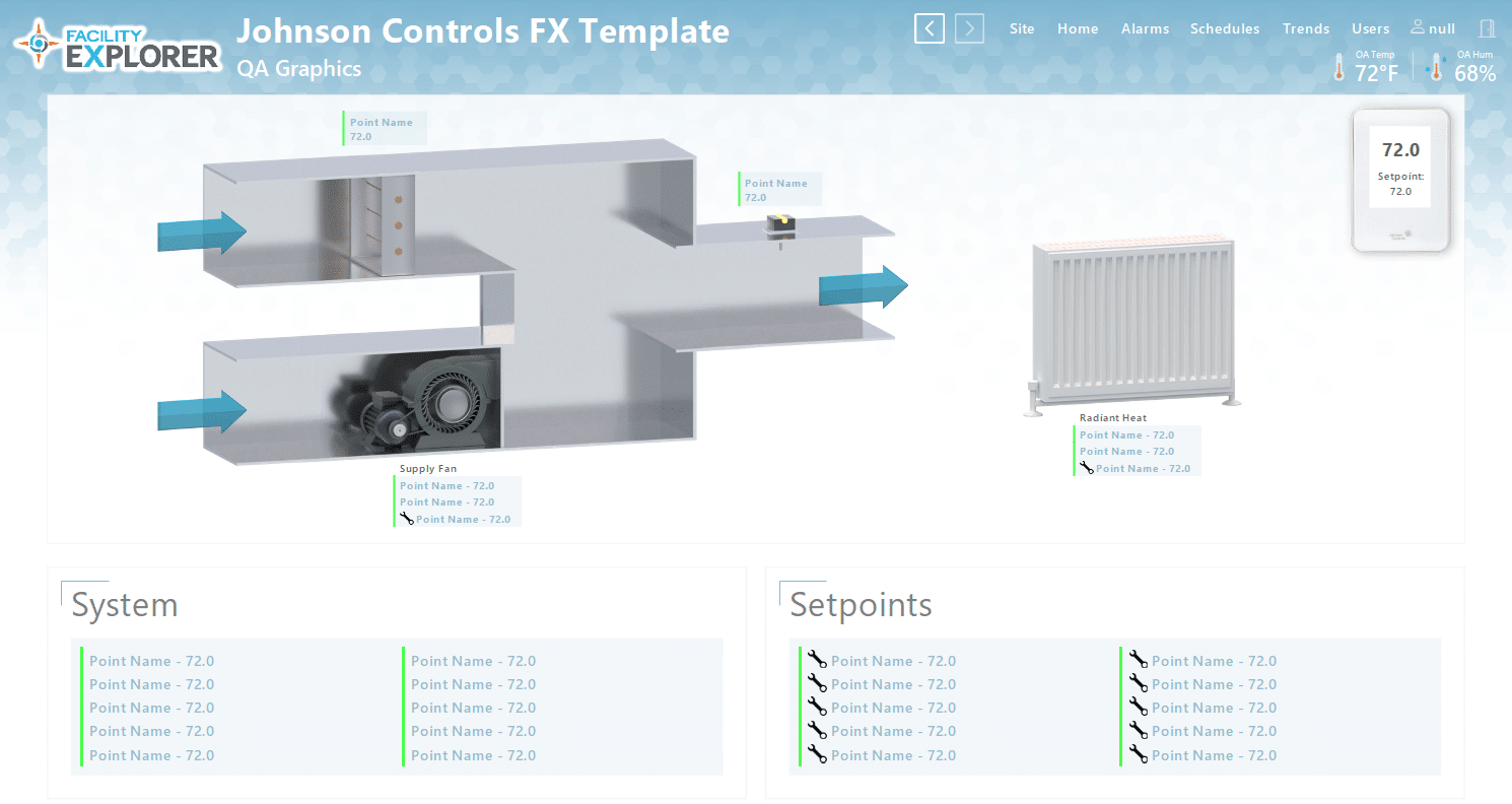
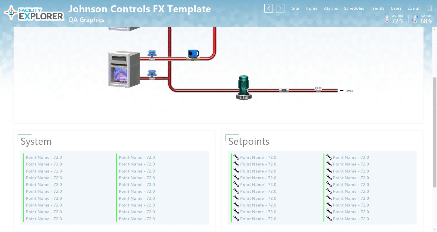
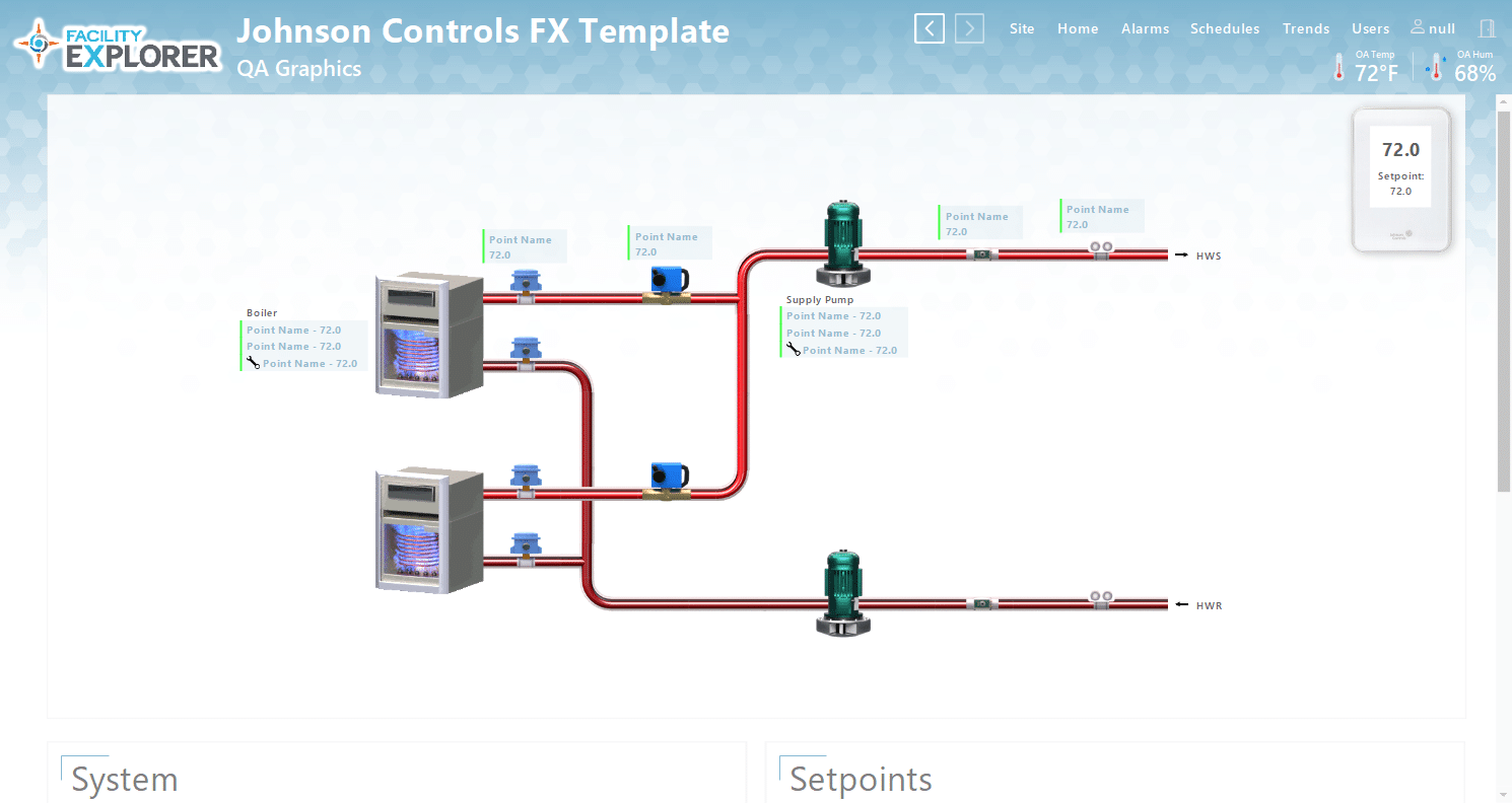
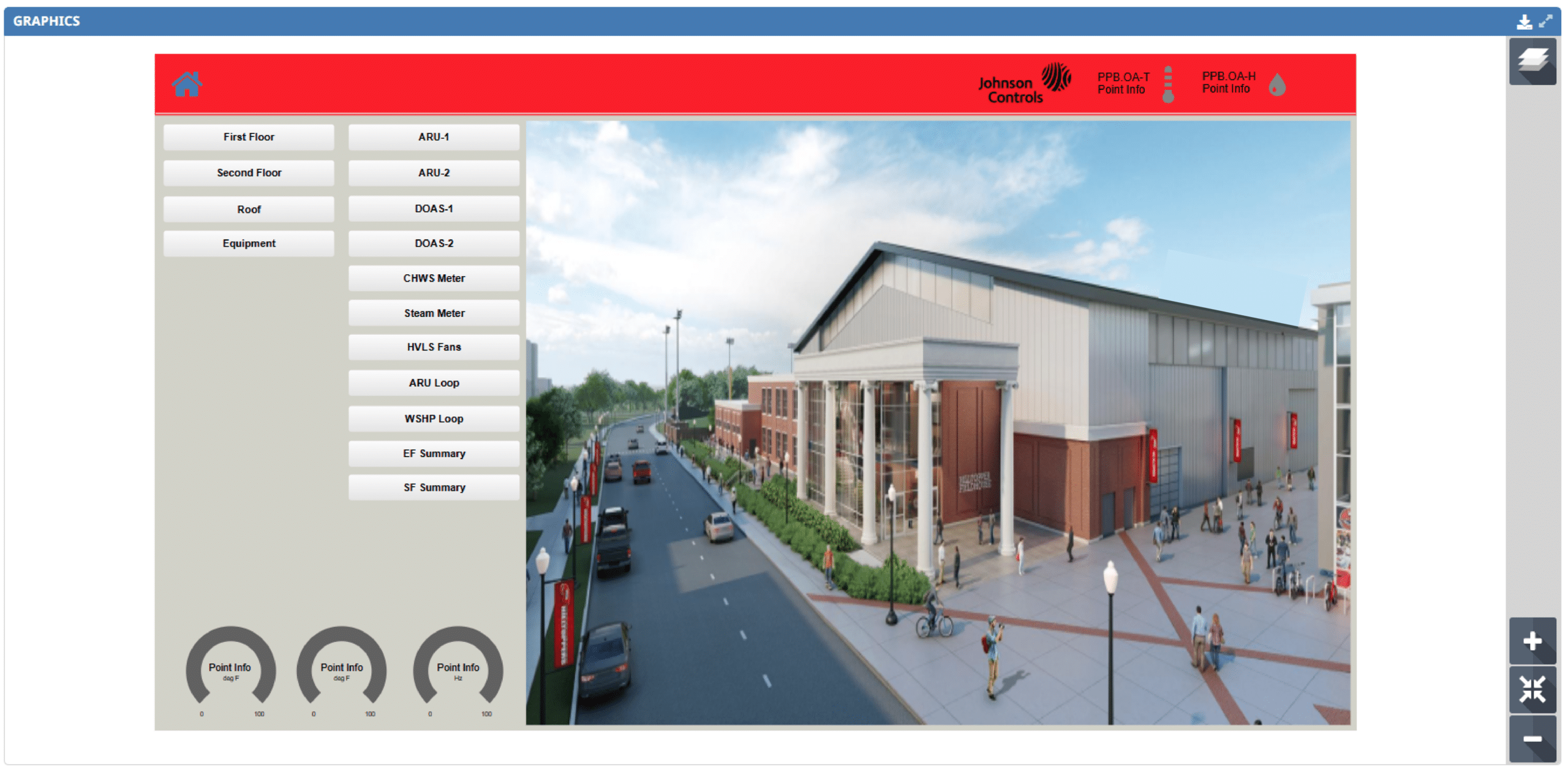
With Facility Explorer (FX), we provide a full range of graphic design and integration services focused on usability, efficiency, and modern system performance. Our customized FX graphic templates go beyond visual upgrades by improving navigation, streamlining workflows, and enhancing the overall operator experience. By incorporating the latest 3D photorealistic graphics from Johnson Controls, we deliver responsive, high-end interfaces that perform seamlessly across all devices while maintaining a familiar and user-friendly experience.
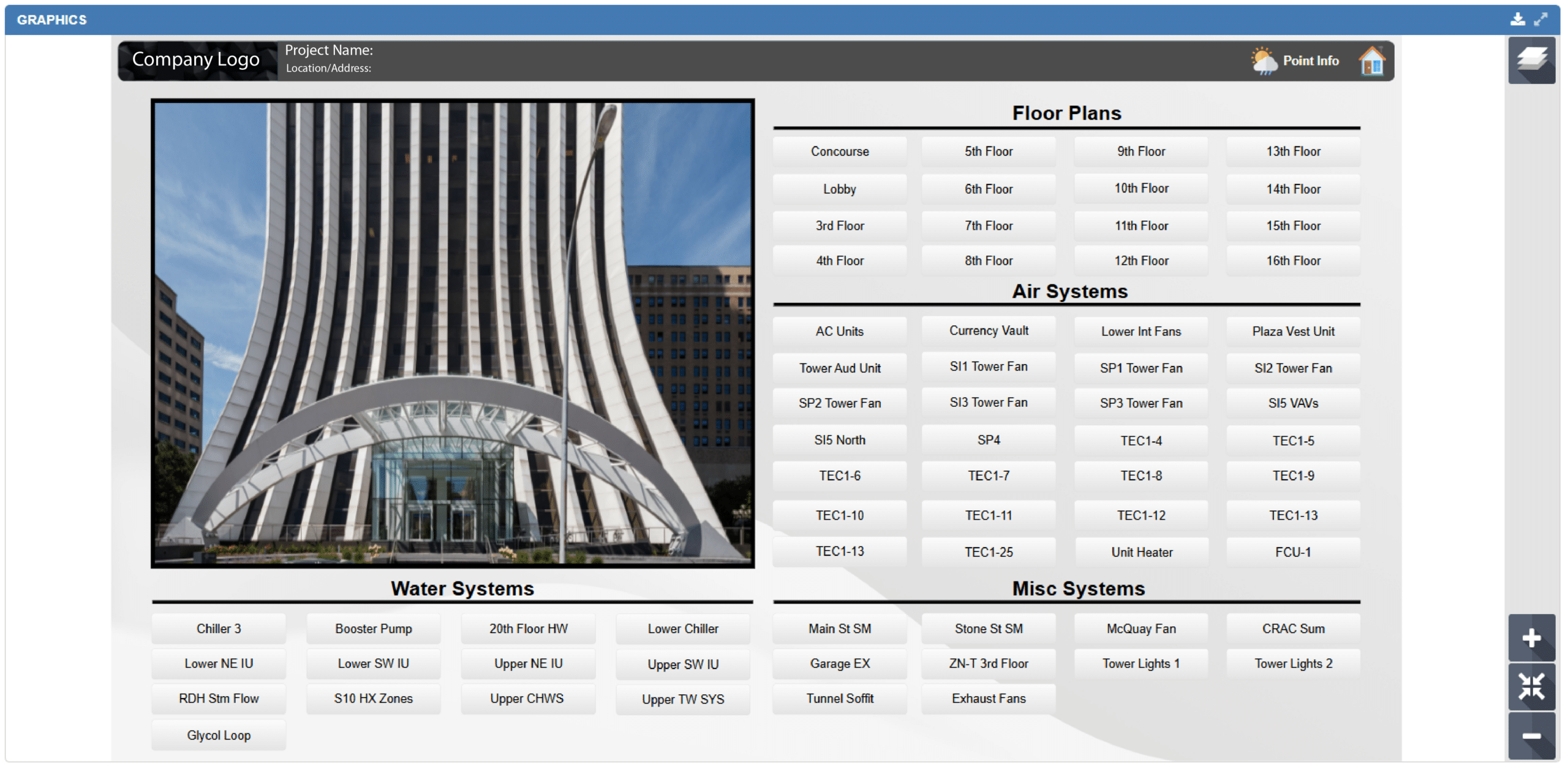
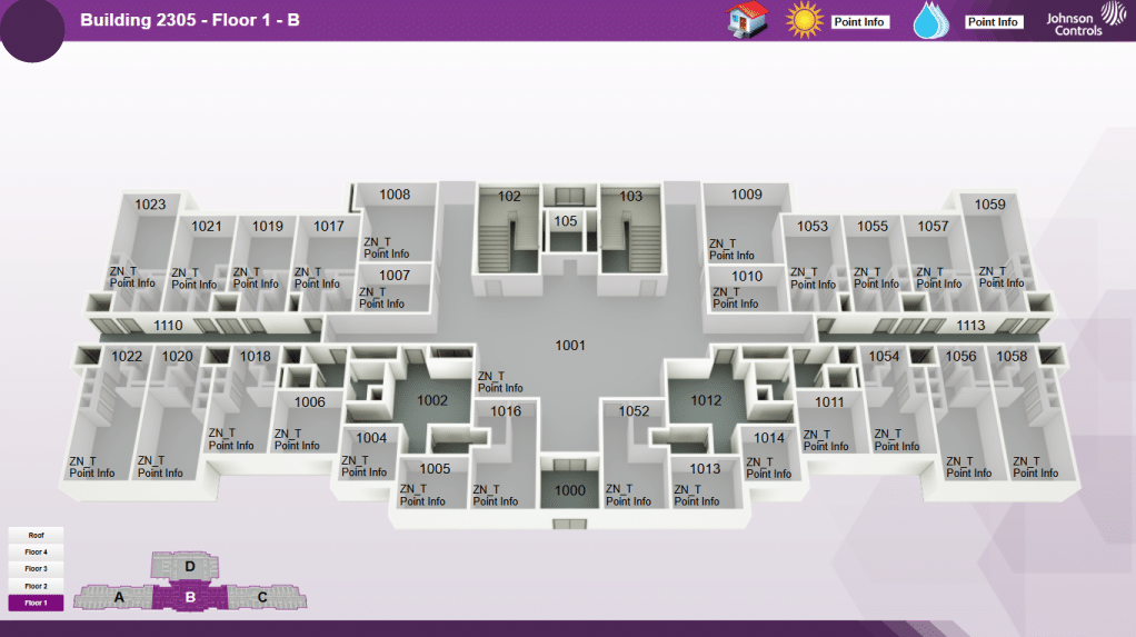
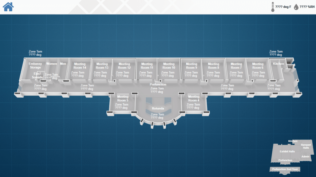
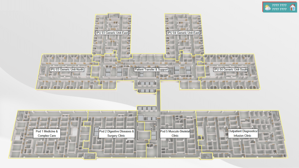
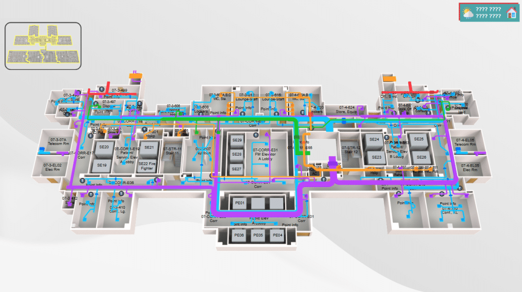
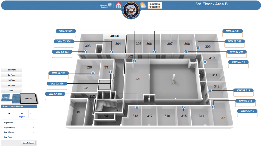
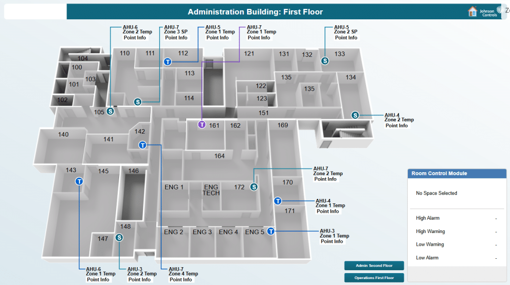
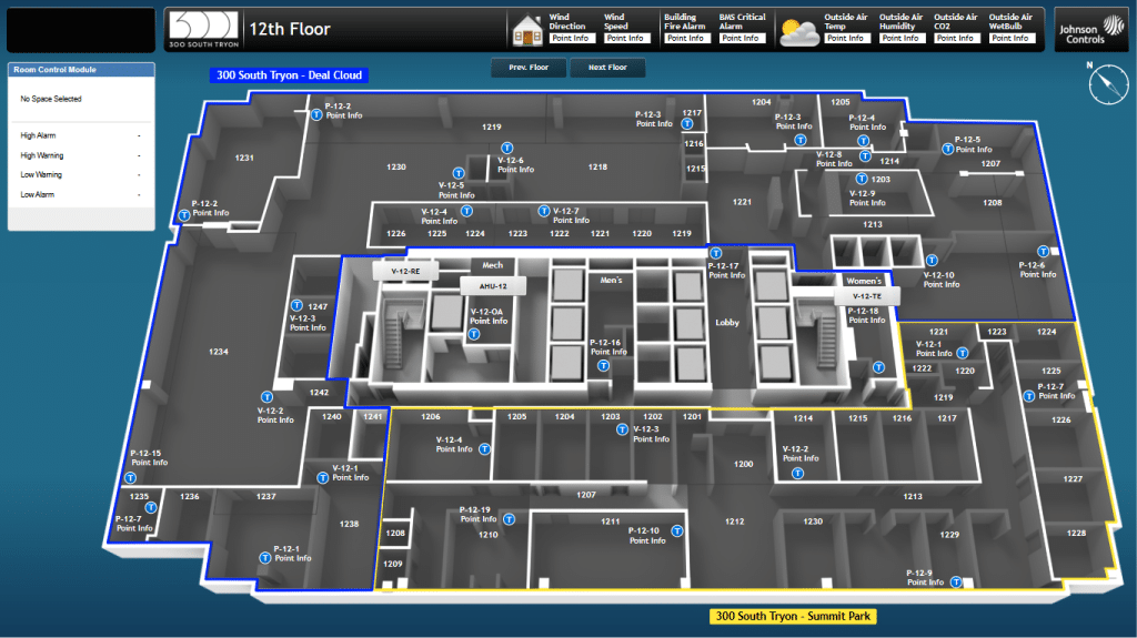
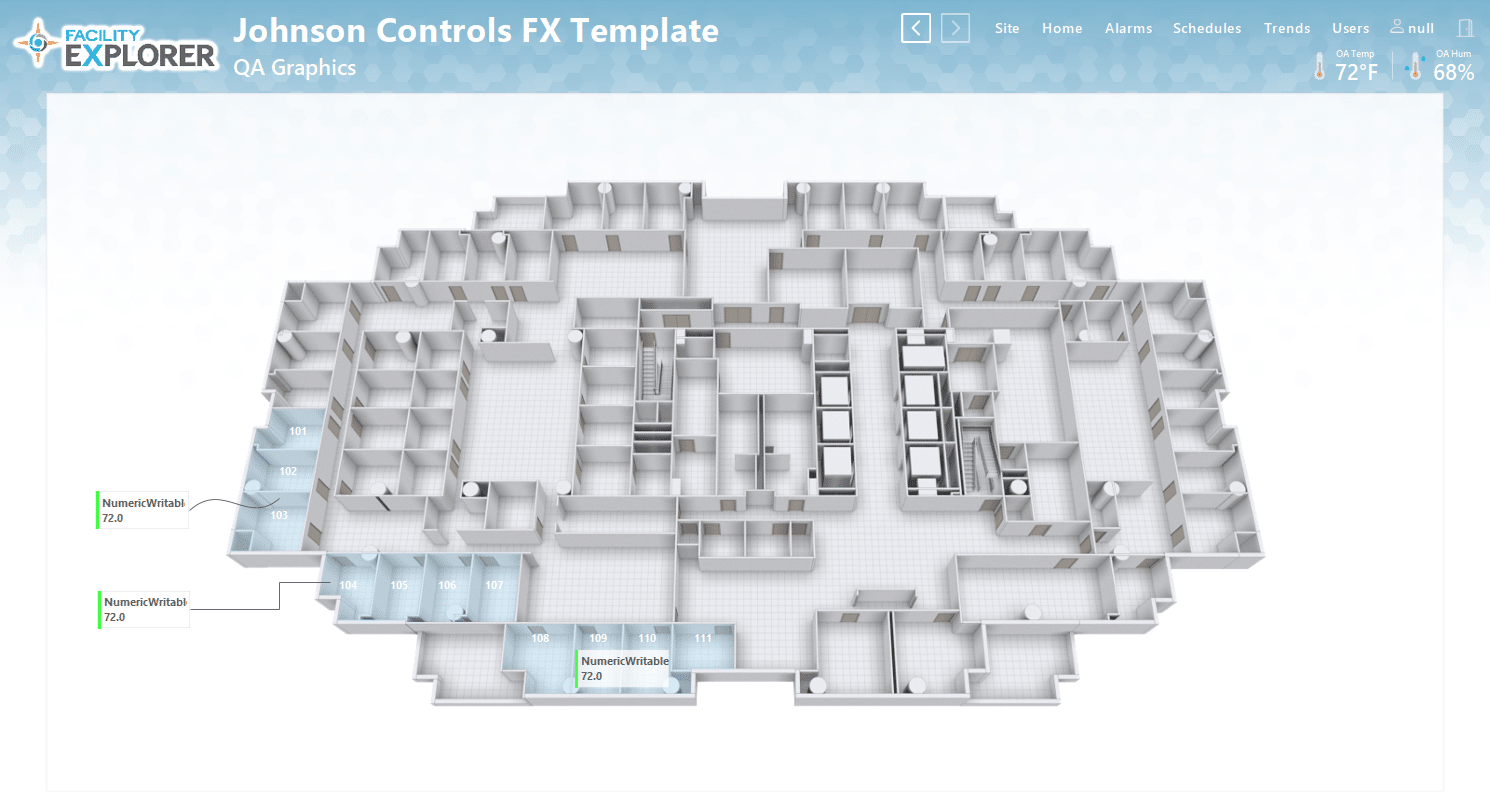
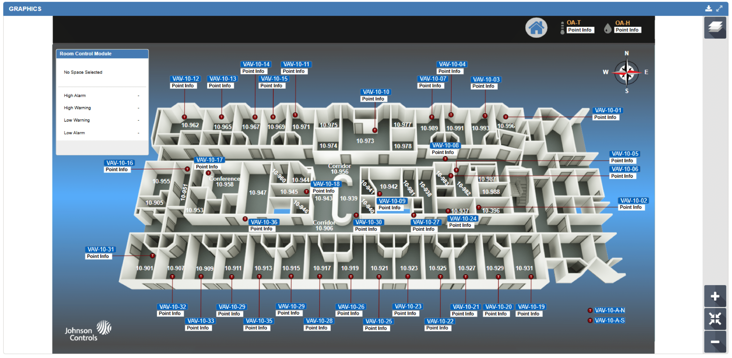
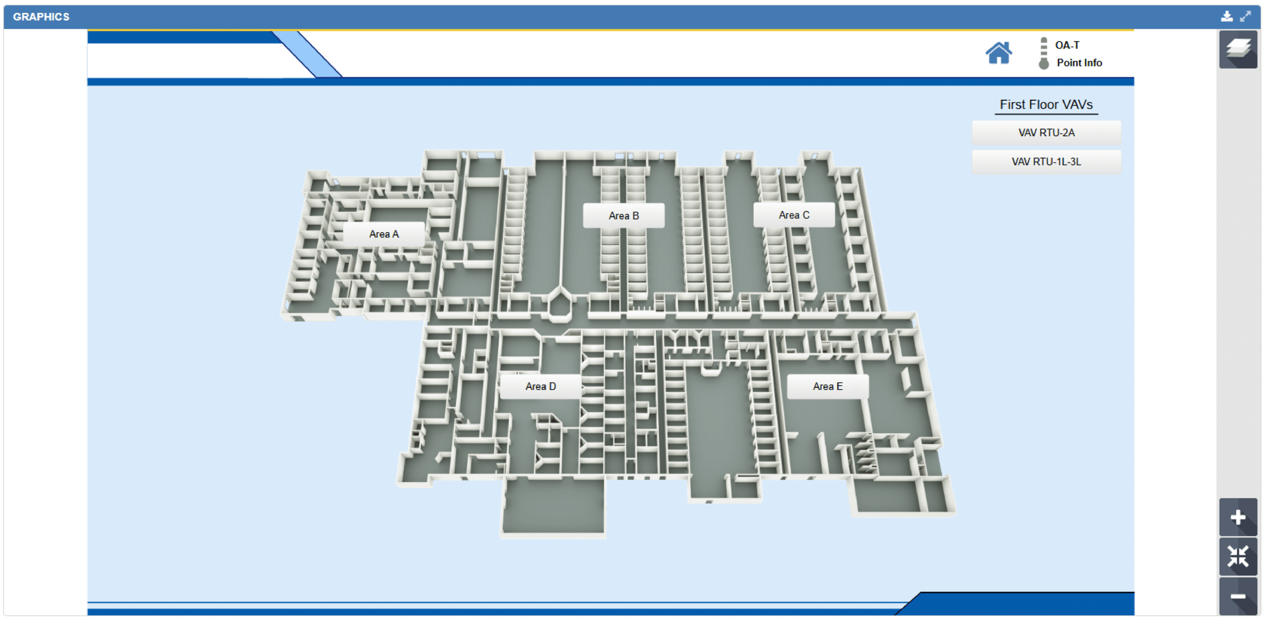
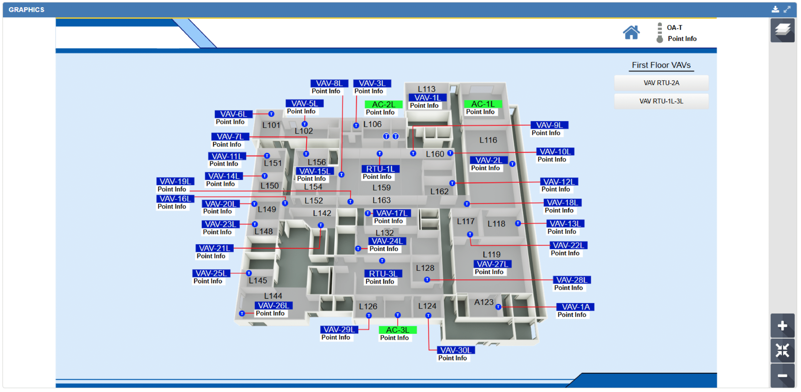
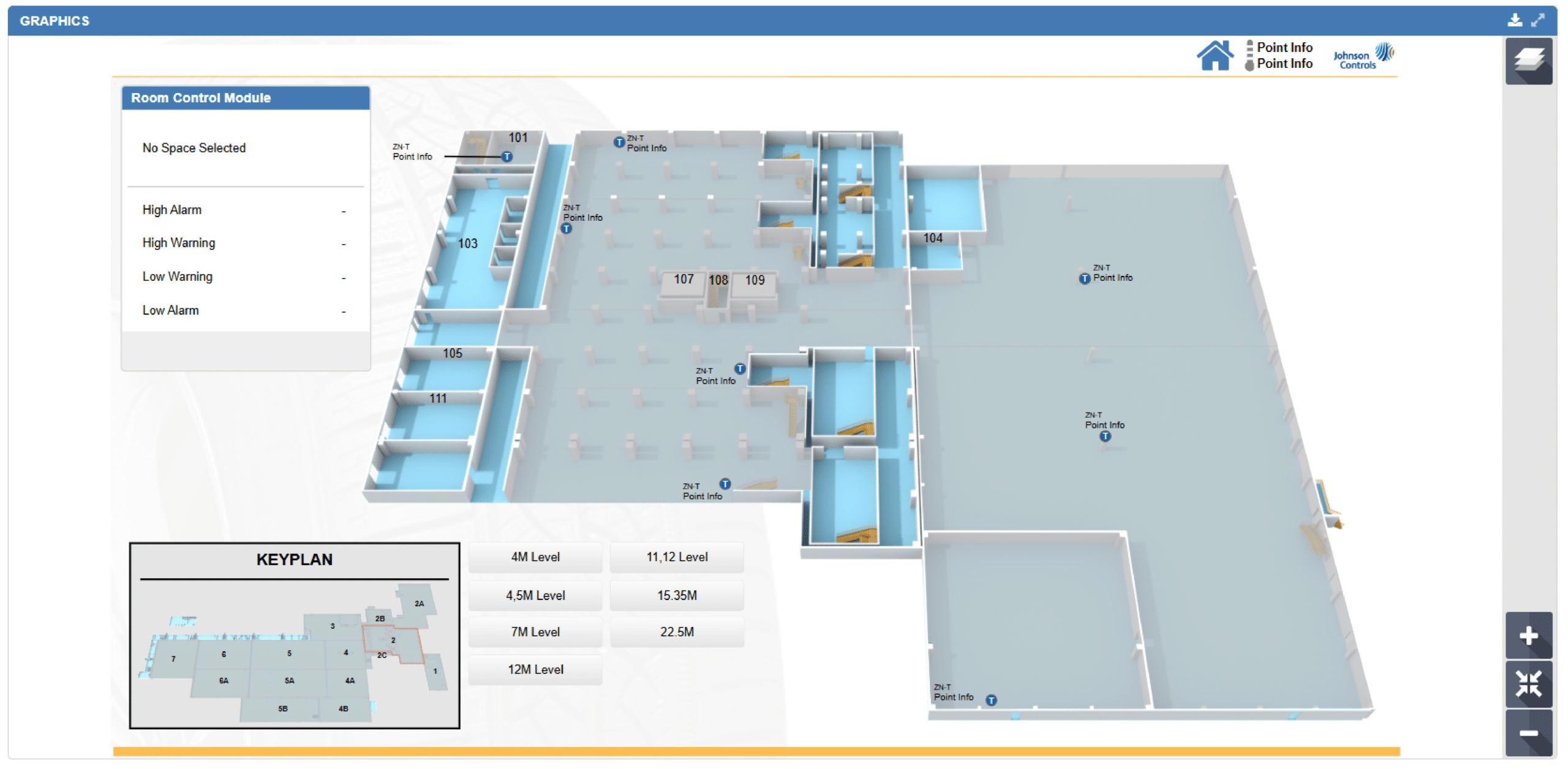
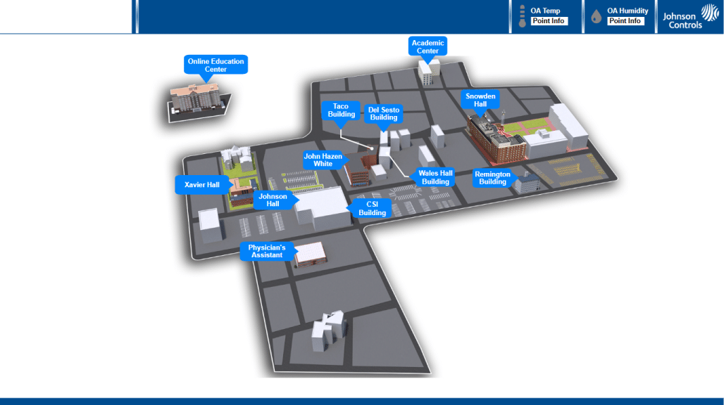
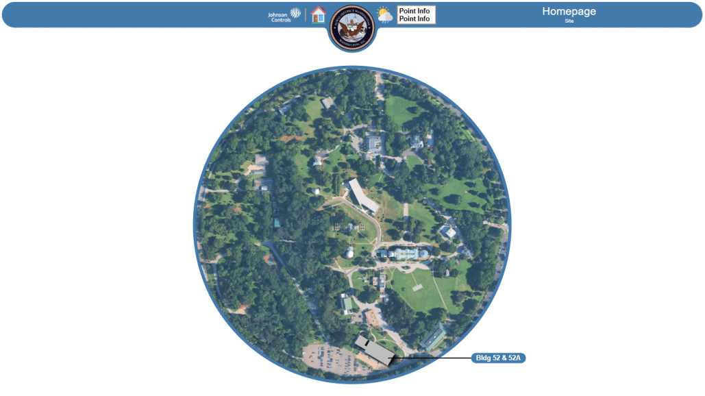
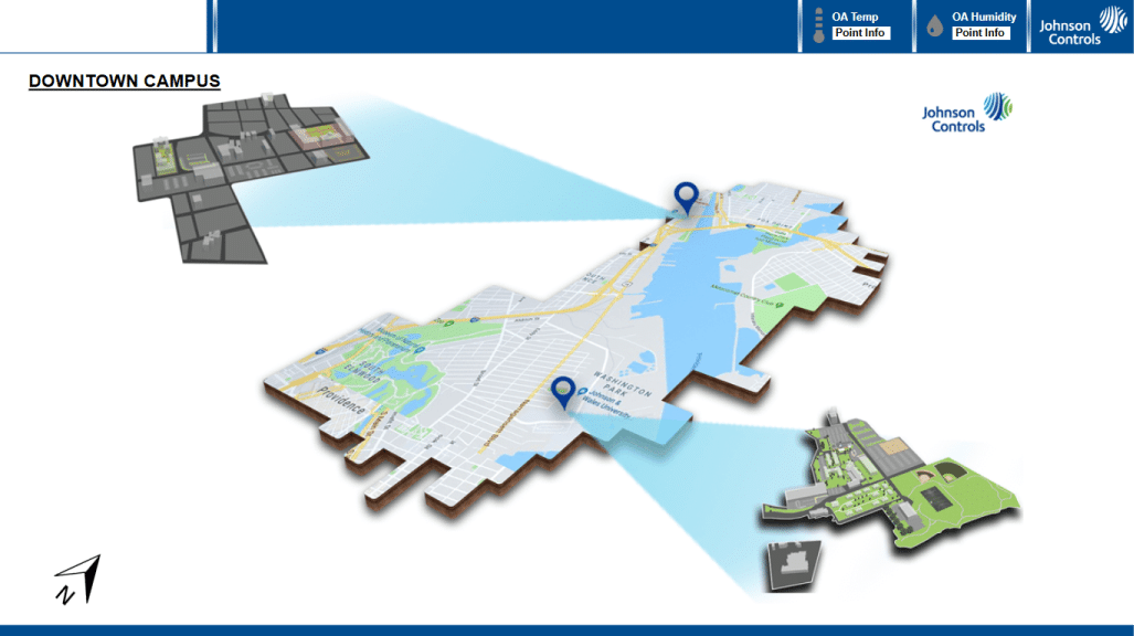
2. FLOOR PLAN SERVICES
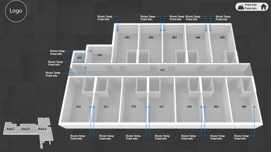
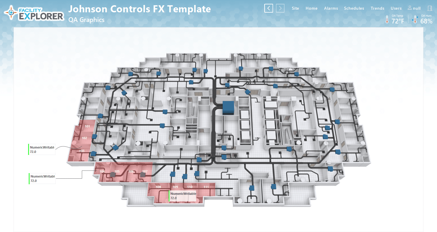
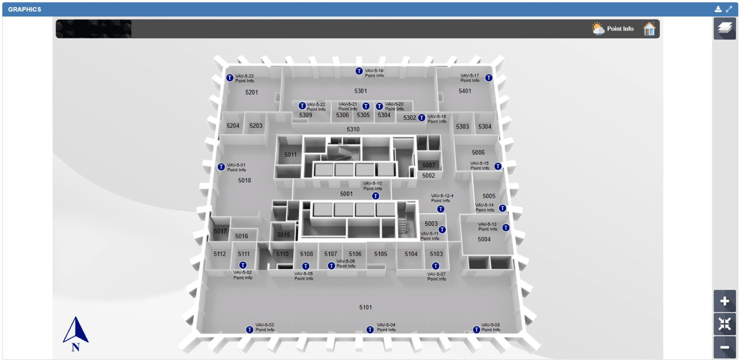
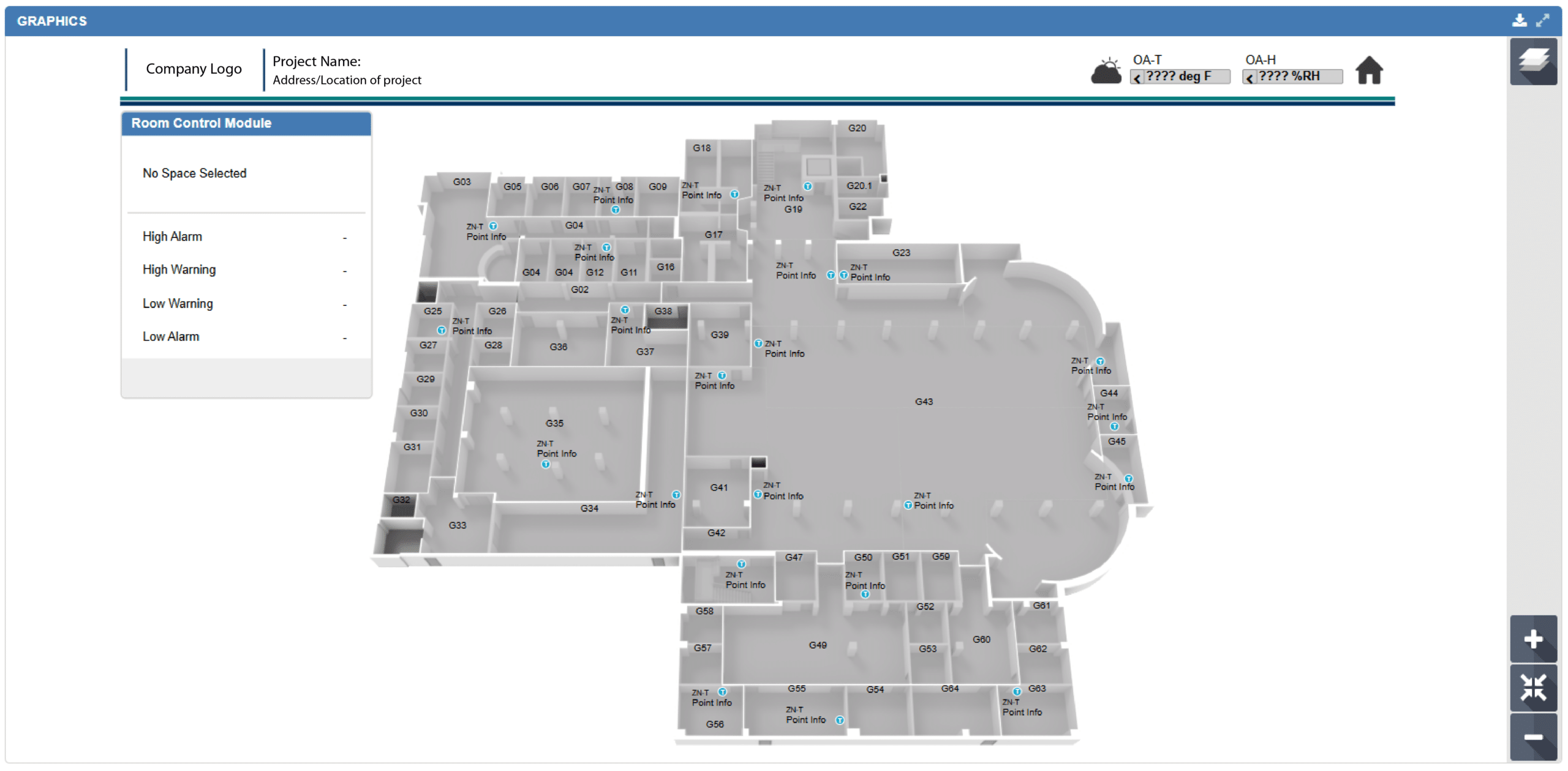
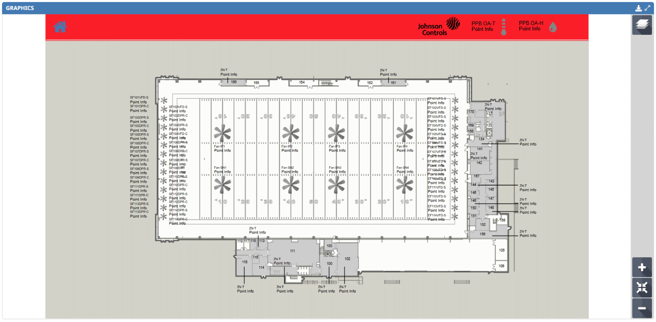
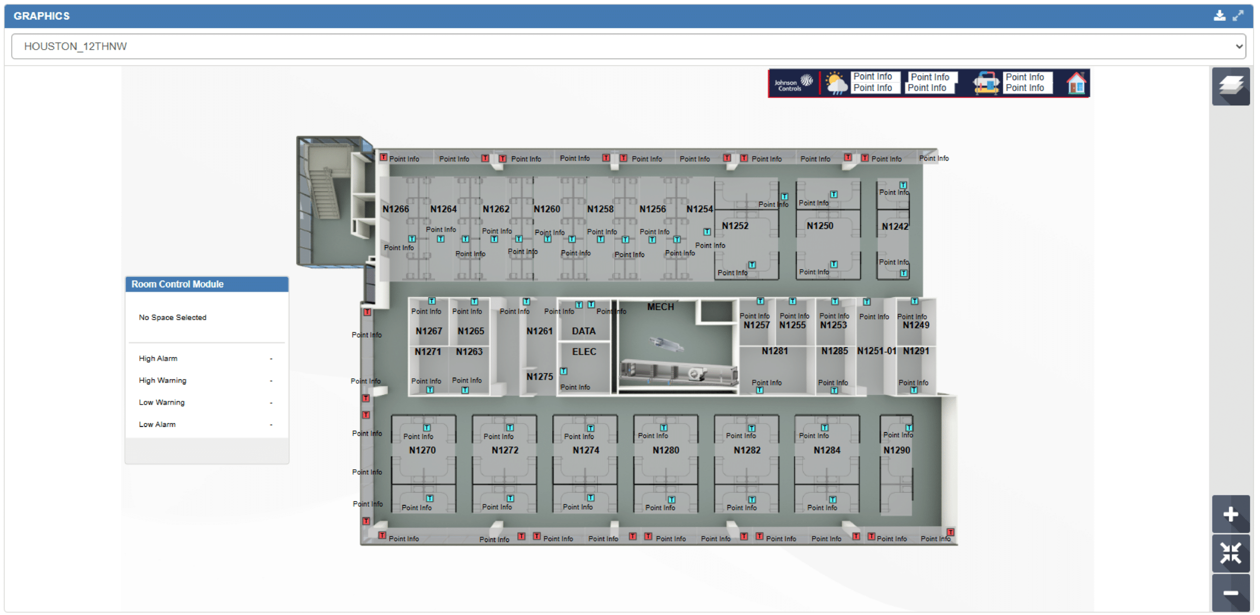
We provide detailed, accurate floor plan graphics designed to improve the visualization and management of building layouts within Metasys UI and Facility Explorer (FX).
Our experienced drafting team specializes in creating floor plans that integrate seamlessly into both platforms while maintaining consistency across an entire project. From standardized layouts and branding to advanced details like ductwork, zoning, equipment, and furniture, we tailor every graphic to match the specific needs of the facility and end users. Whether you need a clean, simplified layout or a highly detailed representation of your building systems, our team can deliver a solution customized to your exact vision.
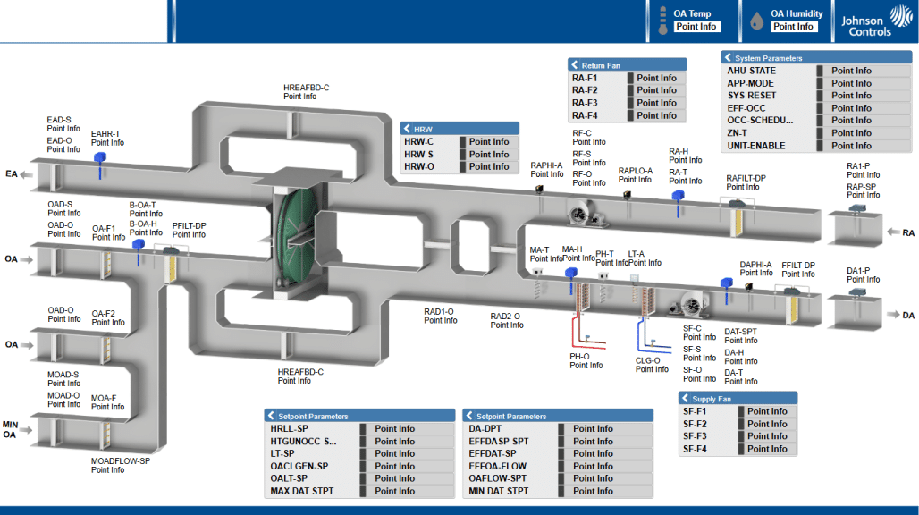
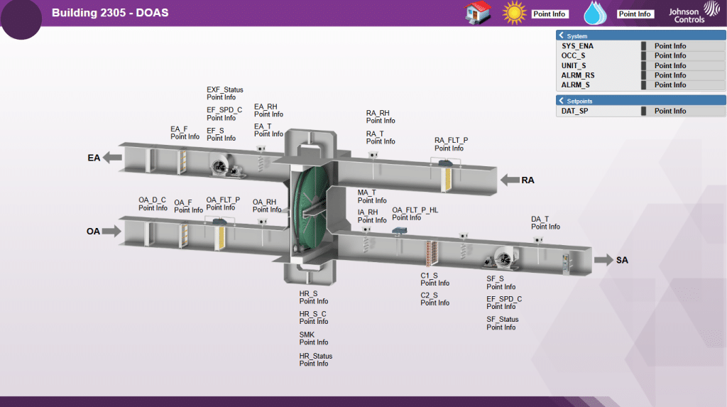
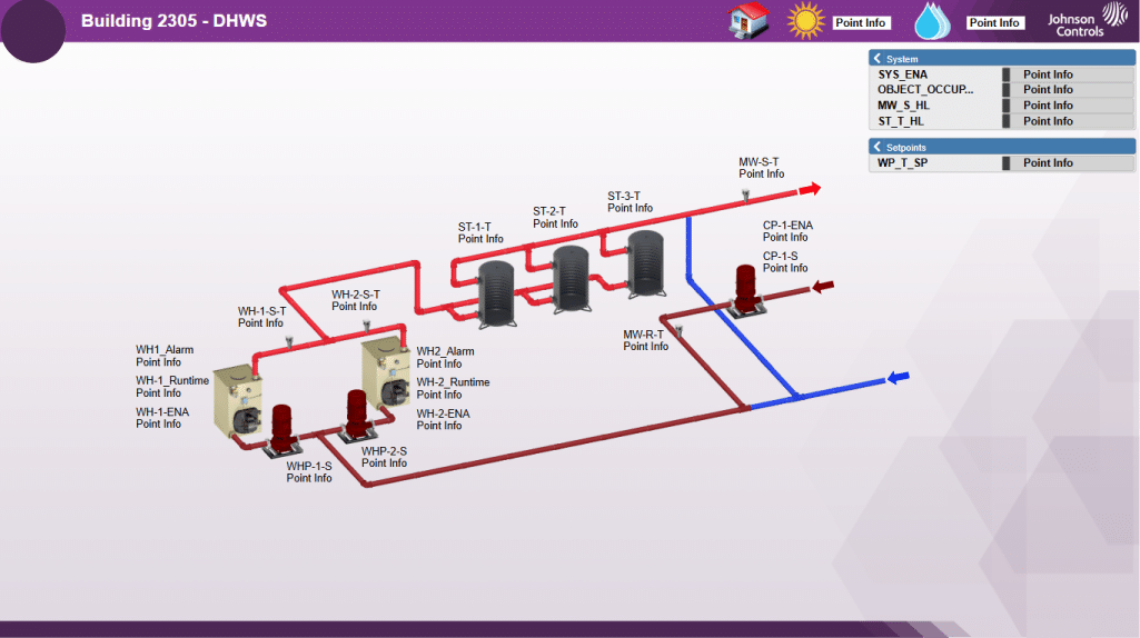
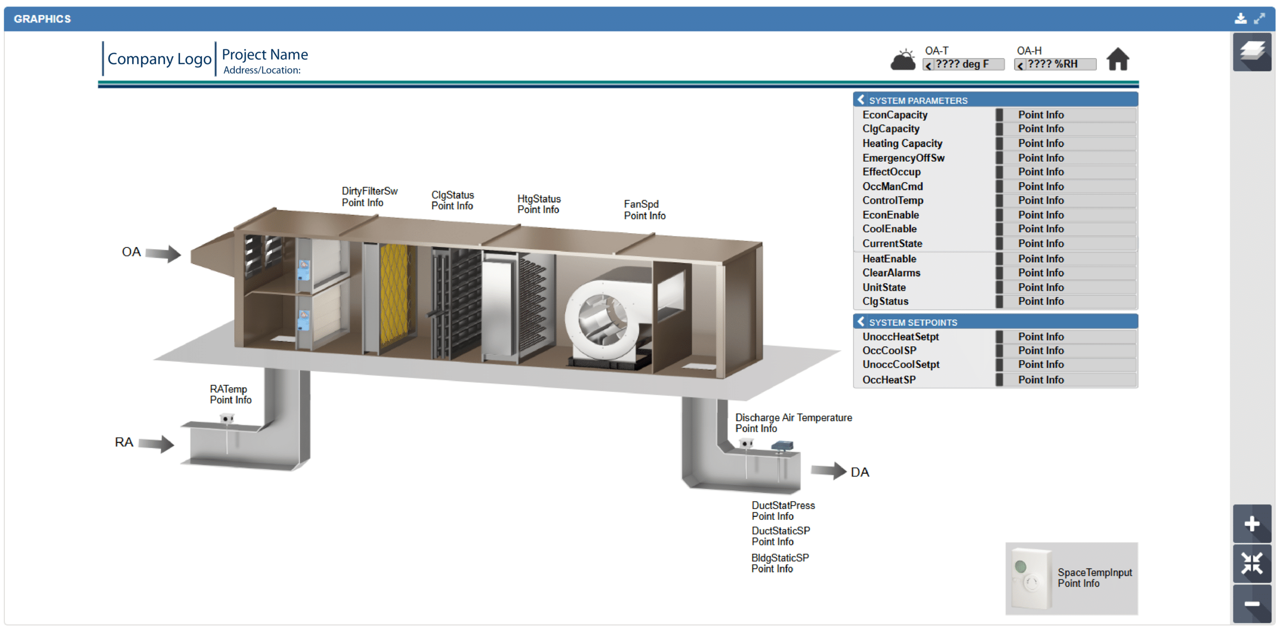
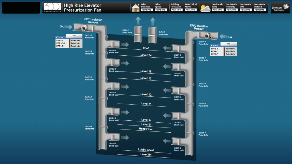
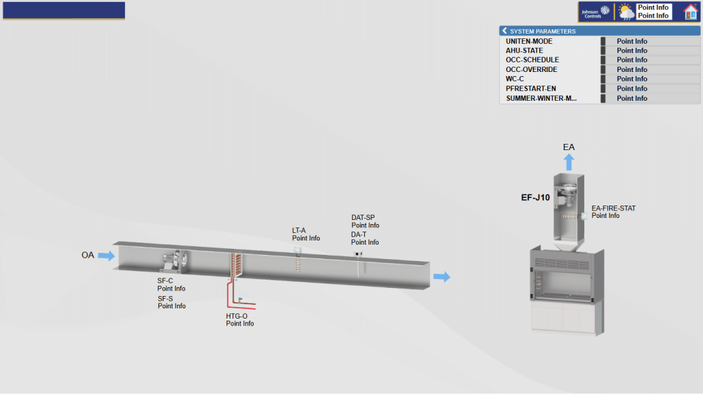
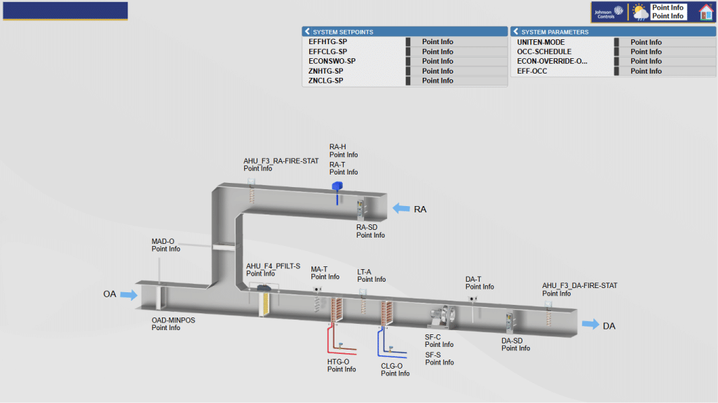
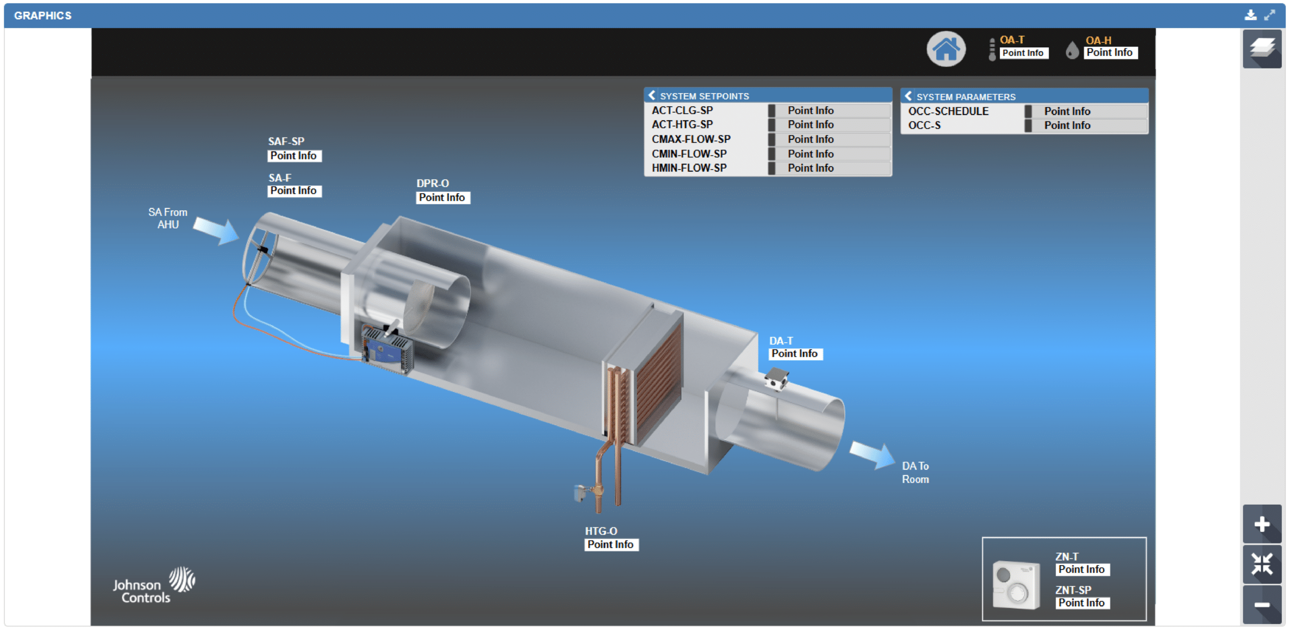
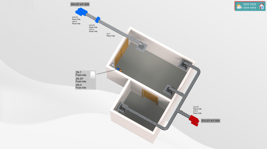
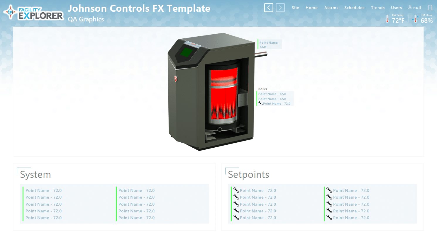
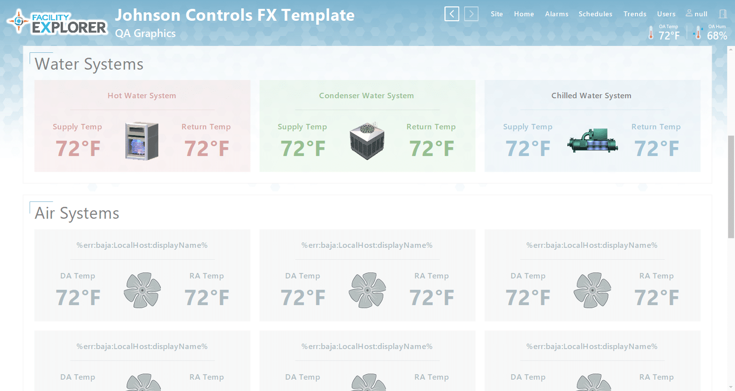
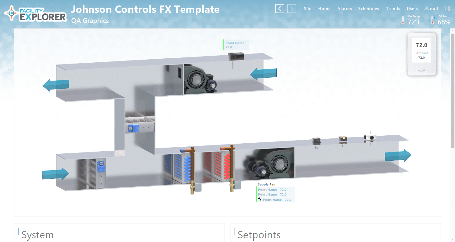
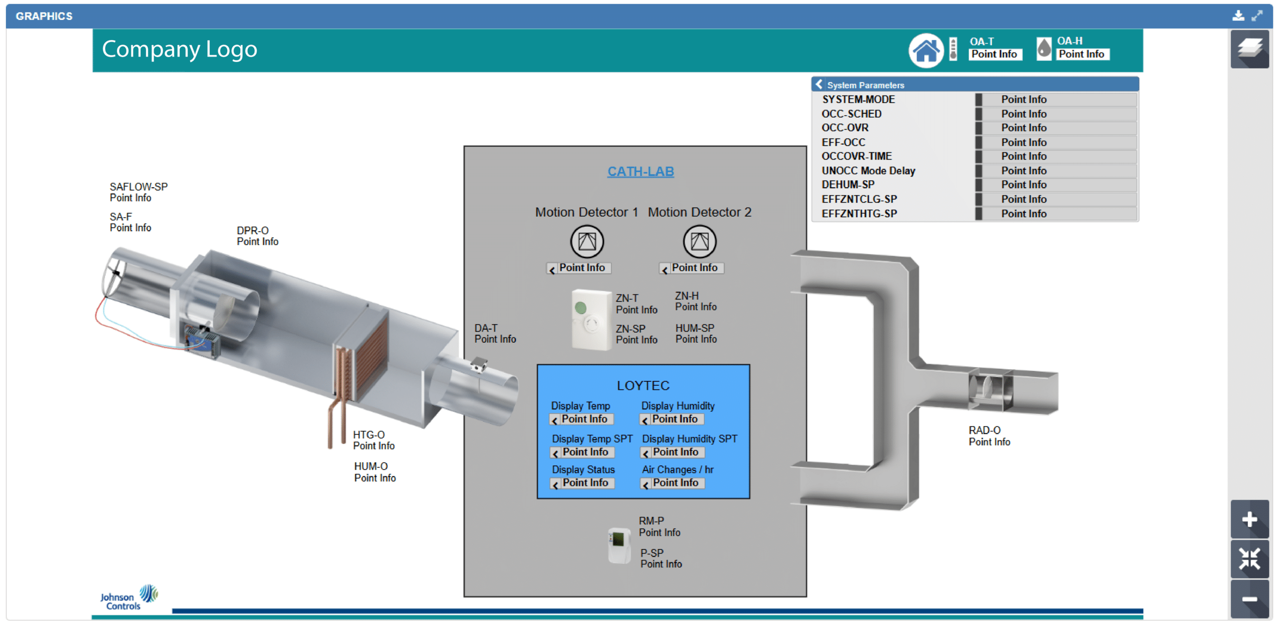
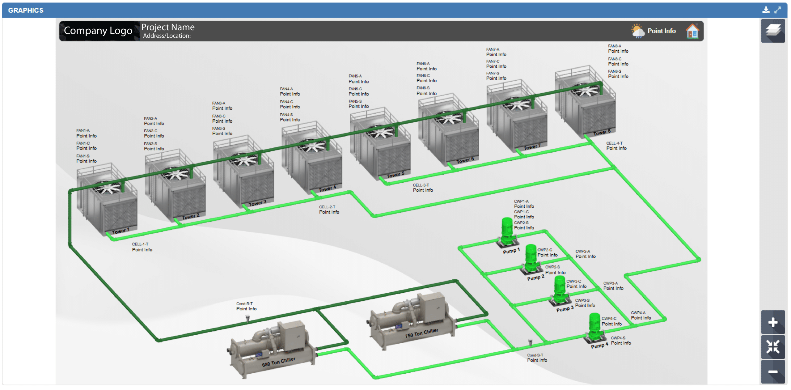
3. 3D EQUIPMENT GRAPHICS
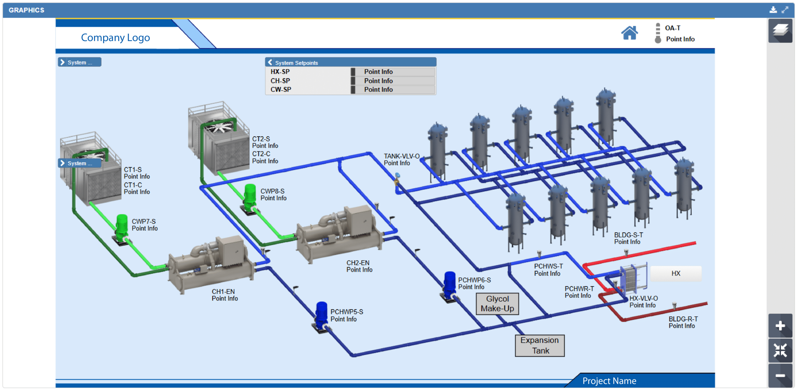
Our team creates highly realistic 3D equipment graphics that elevate the visual experience and improve the understanding of complex system components within Metasys UI and Facility Explorer (FX).
Going beyond traditional graphic components, our true 3D designs provide a modern, lifelike representation of mechanical systems while maintaining full functionality within the platform. Each graphic can be dynamically bound to live data points, allowing for real-time animations and interactive visual feedback based on equipment operation and system status. The result is a more intuitive, engaging, and informative user experience for operators and facility teams.
FLEXIBLE DELIVERY OPTIONS:
Live via VPN Connection
Our team can work directly within your environment through a secure VPN connection, allowing for real-time collaboration, faster implementation, and immediate adjustments throughout the project process.
Database File Transfer
For added flexibility, completed graphics and project files can also be delivered through file transfer directly for your team to implement into your database environment, providing a streamlined and convenient deployment option.
Let's Get Started
Whether your project is large or small, our team possesses expert knowledge of the MUI platform, ensuring that we can meet and exceed your expectations. Trust QA Graphics to deliver exceptional graphic design services for your Johnson Controls systems. QA Graphics is an authorized vendor, our vendor number is 297586. For inquiries, please reach out to us at [email protected].
Our Customers
QA Graphics did an exceptional job on the graphics for our recent project, which was full of confusing and complex systems. You would almost think that QA Graphics was part of the project from the beginning. In fact, I have been surprised many times to find that little obscure things were picked up on that I was sure would be missed. I REALLY appreciate the work QA Graphics did on this project.
JAMES PLATANIA
Senior Systems Engineer
– Johnson Controls Building Solutions, LLC –
I would like to throw a huge shout-out to you and your team for all the hard work on the project. After downloading the new MUI package we expected to see problems and were prepared to come back to QA with a bunch of fixes. This was not the case at all. QA really nailed it on this one and we at JCI are so thankful that you are part of the team!! This was by far the smoothest package that we have had to drop in and it really made us look good in front of this customer. This site has now become a showcase piece for future MUI sites and we are excited to show off the work that was done. Again, thanks so much for all the hard work and please let your team know how much we appreciate them going the extra mile to get this done in such a tight time frame. Looking forward to continuing the relationship and growing together as the future brings on more exciting projects.
Brett C.
Account Service Representative
– Johnson Controls Building Solutions, LLC –
Our Latest Posts

UI and UX continue to be undervalued in the building automation system (BAS) industry. We are seeing a shift at [...]

QA Graphics has officially launched QAGFoxhound, a desktop application engineered for the Tridium Niagara platform that assists system integrators in [...]

At QA Graphics, our mission has always been clear. We help system integrators deliver better building automation graphics through experienced [...]