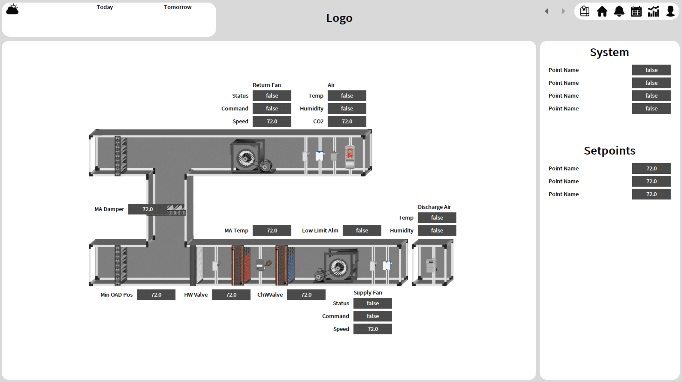
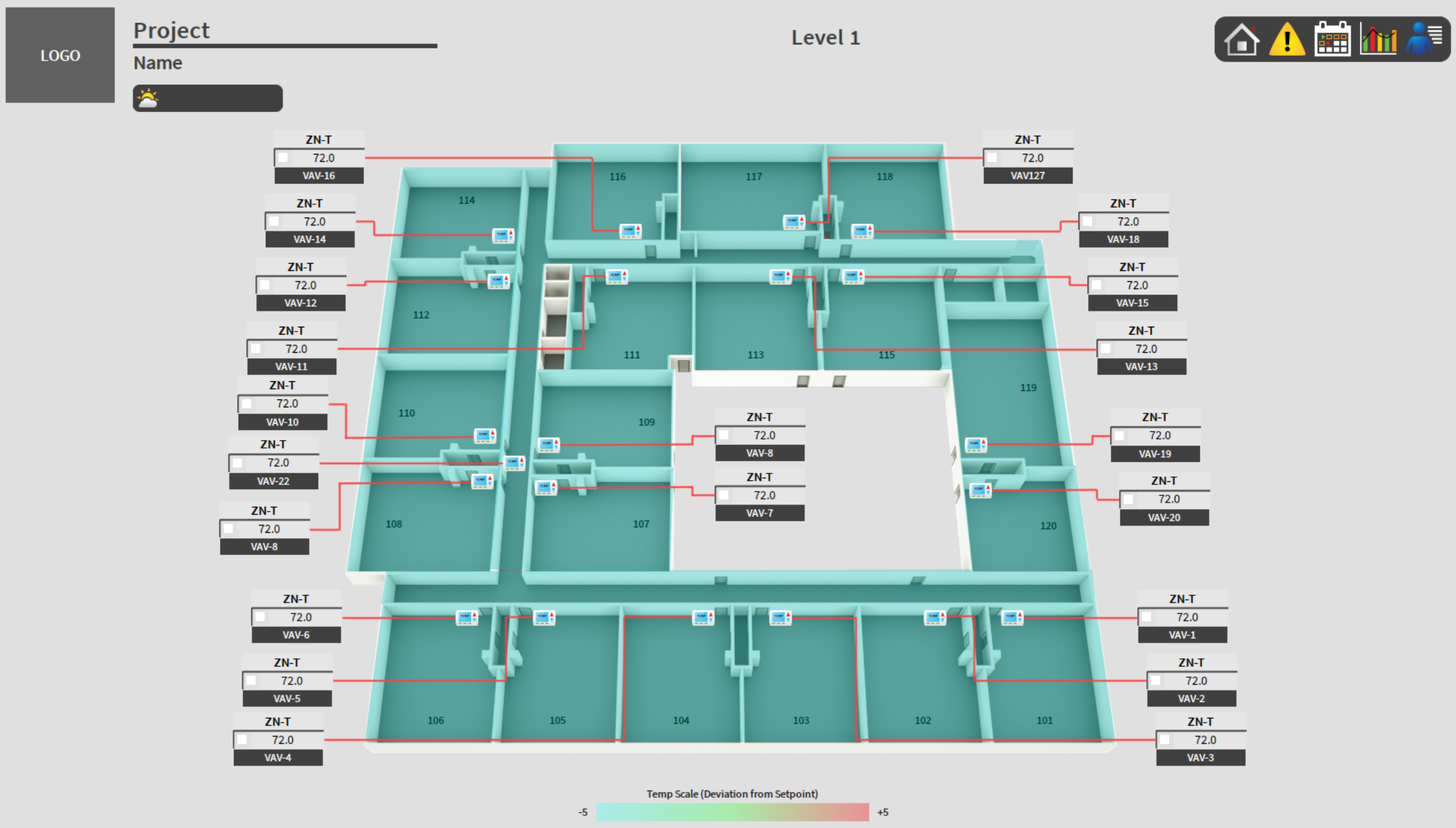
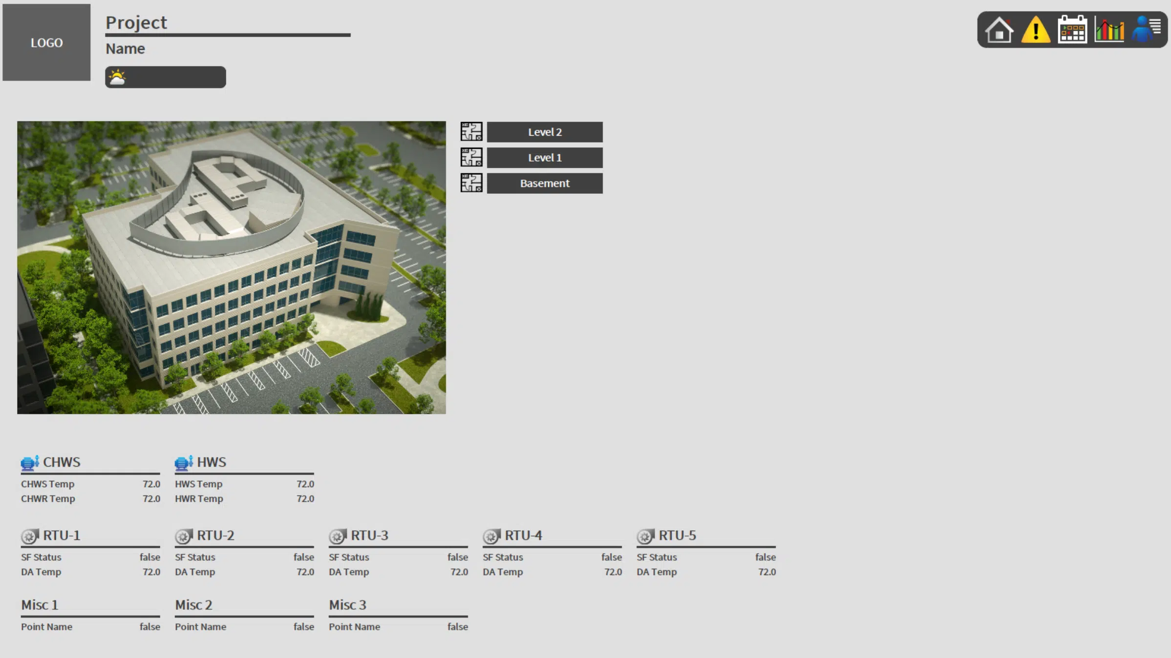
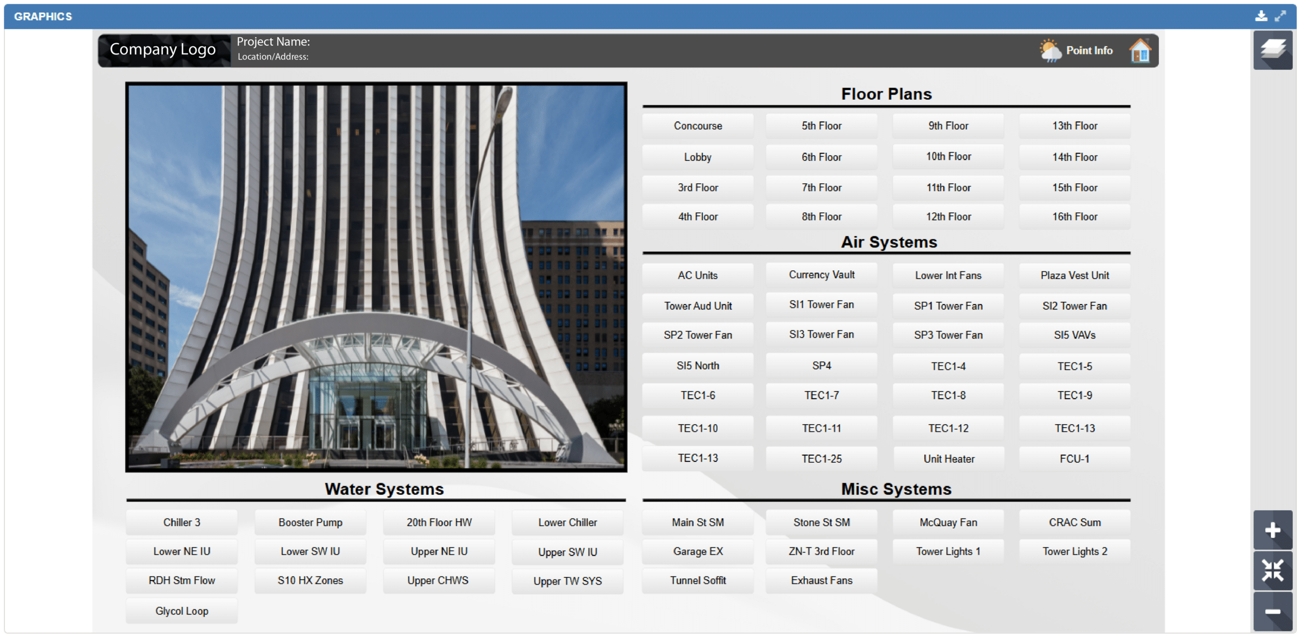
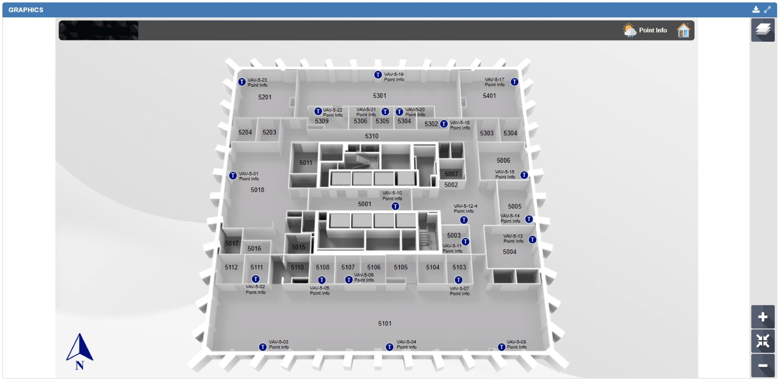
BAS Graphics
QA Graphics specializes in outsourced BAS graphics for system integrators across the building automation industry. Our team of building automation specialists and designers has nearly two decades of experience and has built custom libraries for six of the industry's largest control companies, delivering system graphics, symbol libraries, and floor plan graphics ready to drop into your platform.
An Overview of Our BAS Graphics
Our highly skilled team is proficient in providing backgrounds and point implementation to your database in Johnson Controls, Schneider Electric, and Tridium systems, both “offline” and through remote access. By outsourcing your BAS graphics needs to our dedicated team, you can significantly reduce delivery time. QA Graphics offers unmatched expertise and cutting-edge technology, setting us apart as the best BAS graphics provider.
Establish a company standard that prioritizes a creative look and feel for your clients by leveraging our expertise. Let your team concentrate on programming while we handle the BAS graphics, enabling you to enhance ROI by saving time and budget on graphical software.
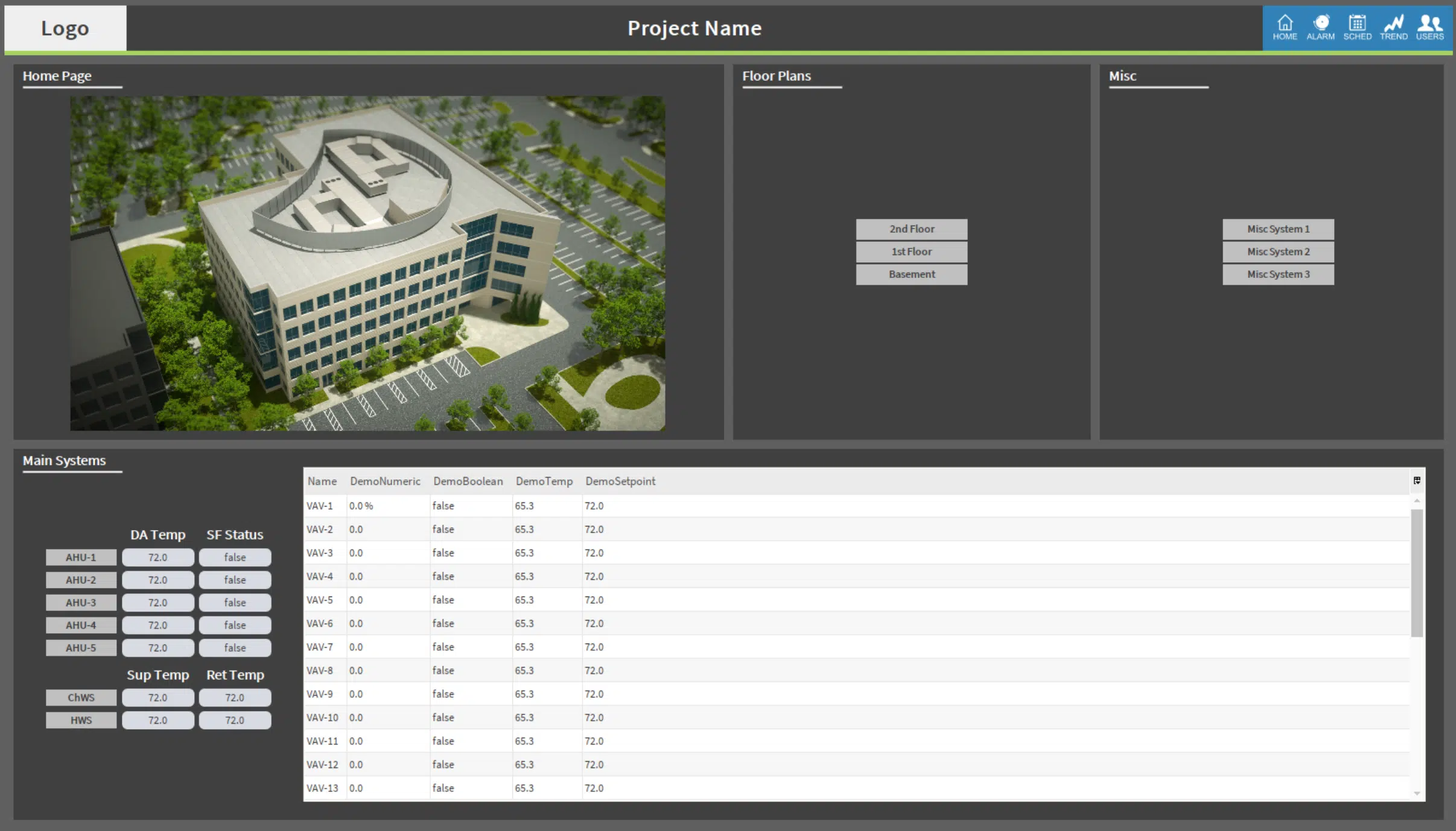
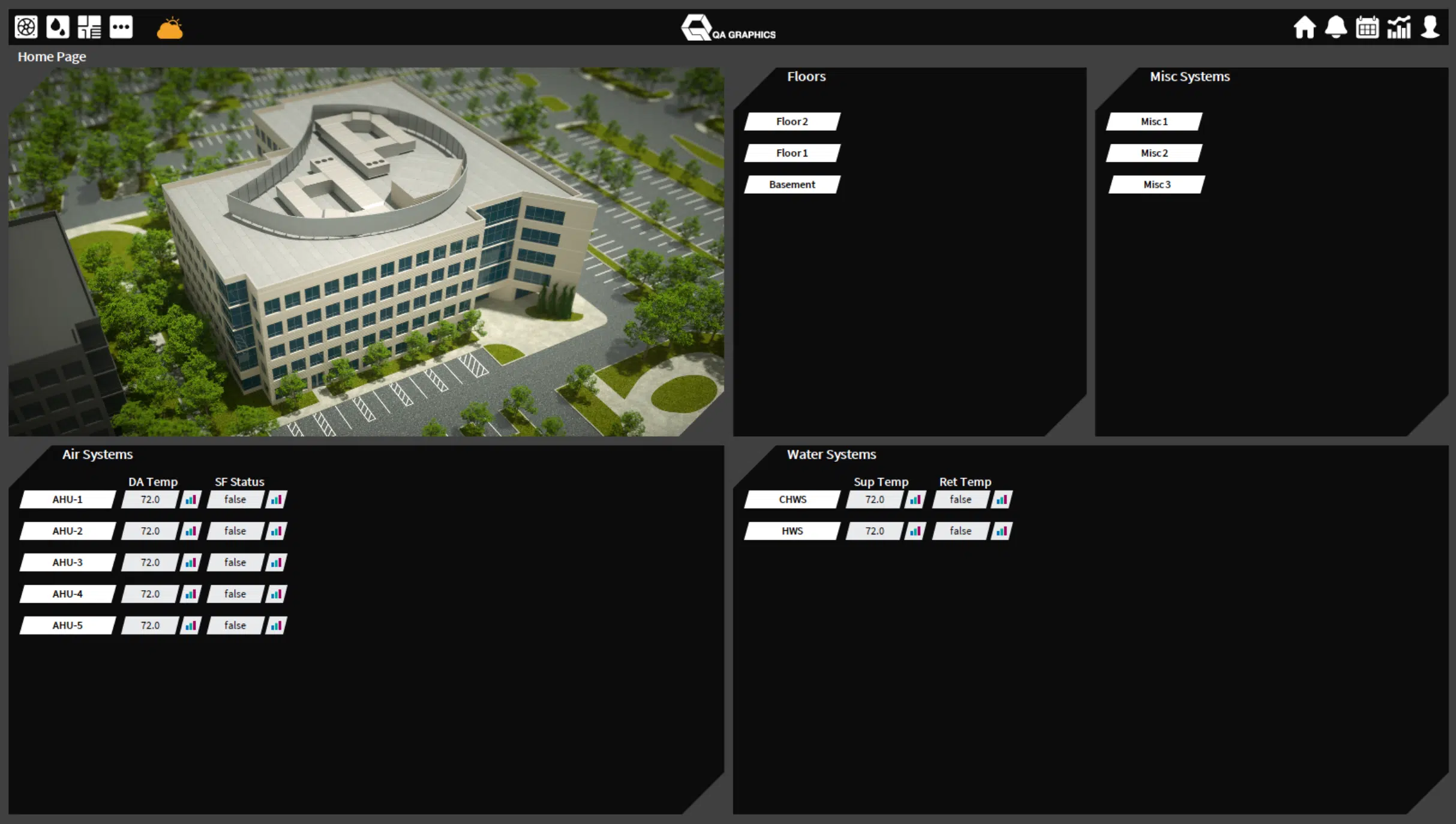
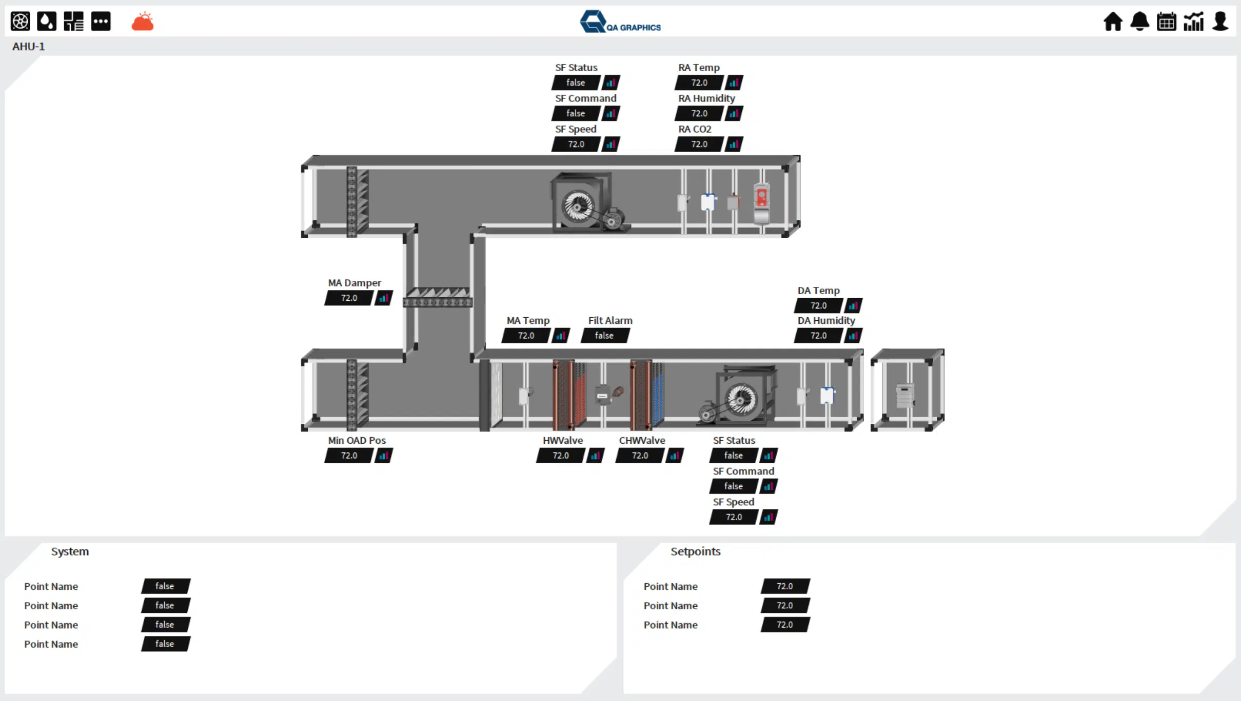
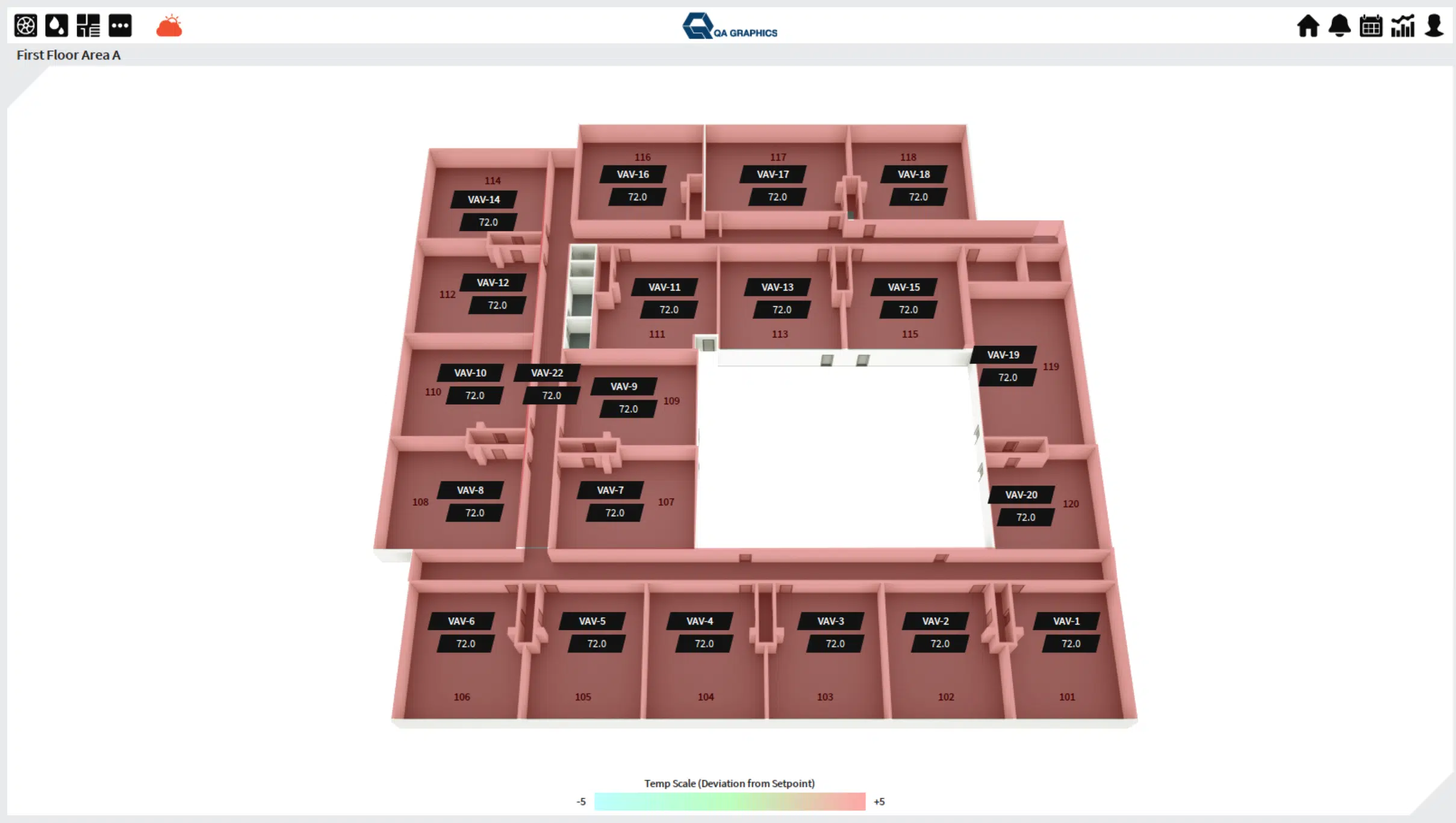
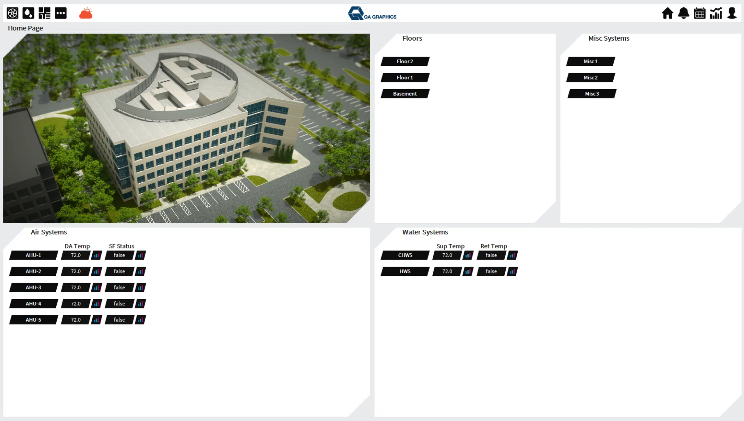
QA Graphics: BAS Graphics Overview

Learn More About Our Full Suite of Services
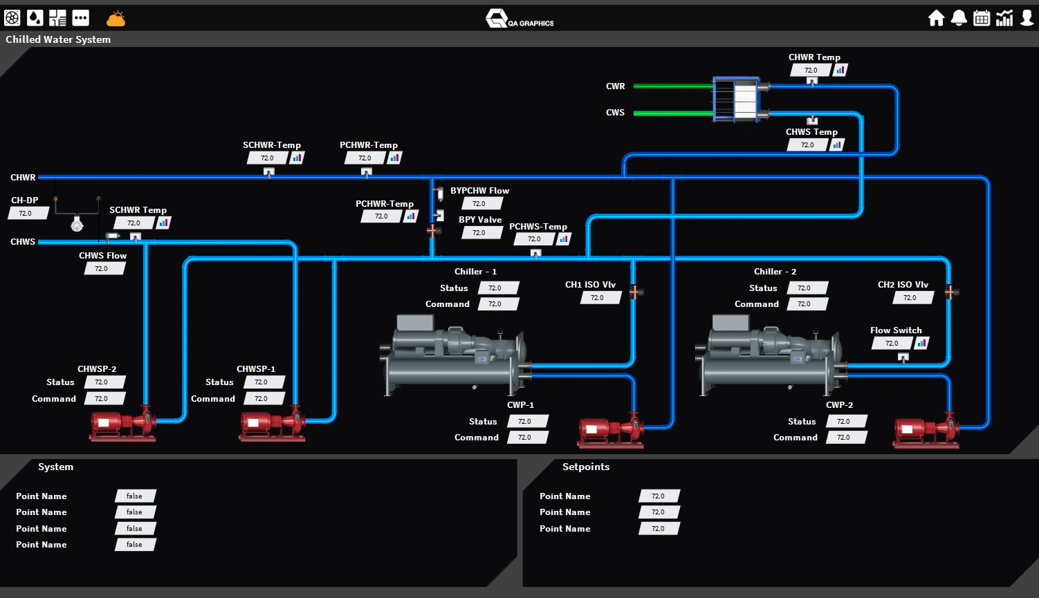
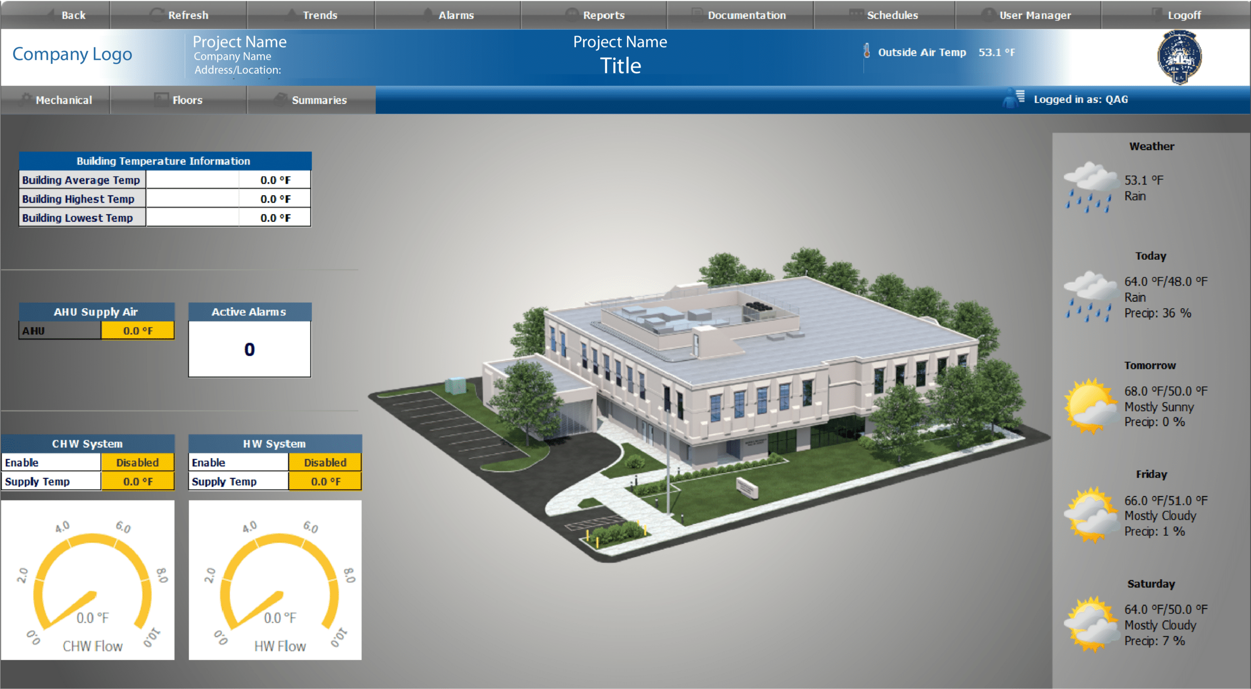
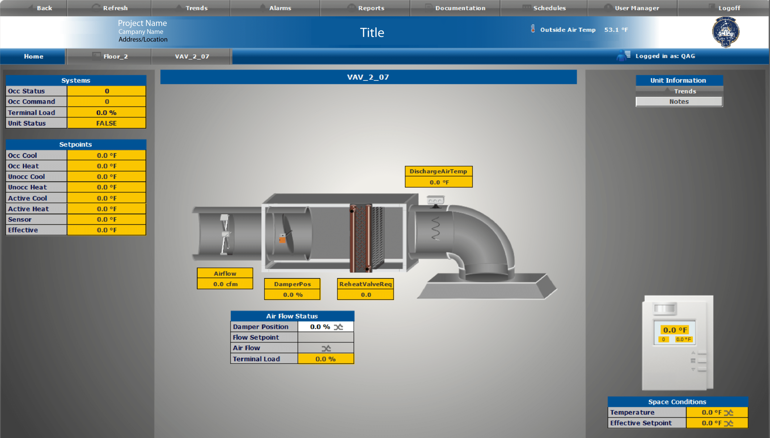
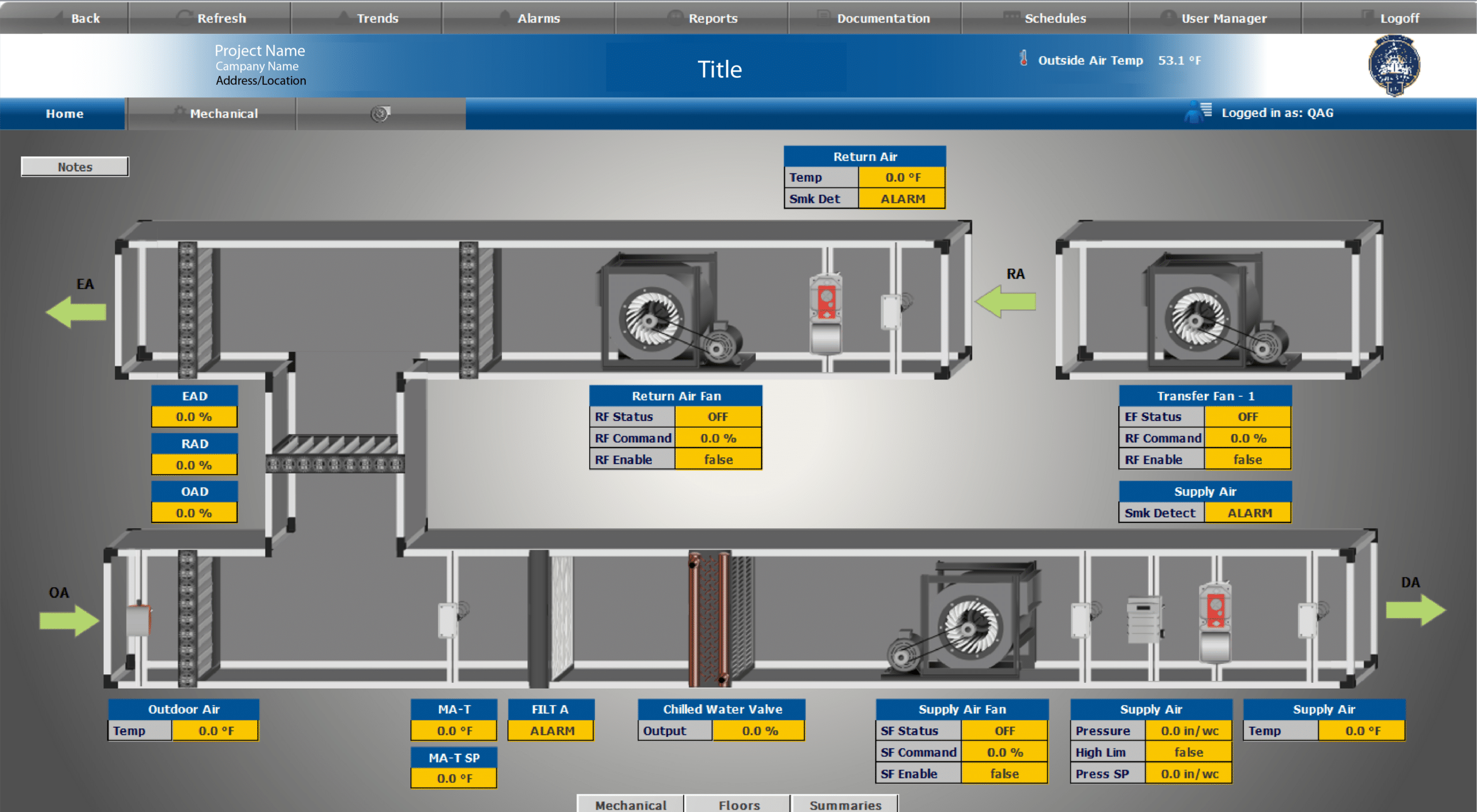
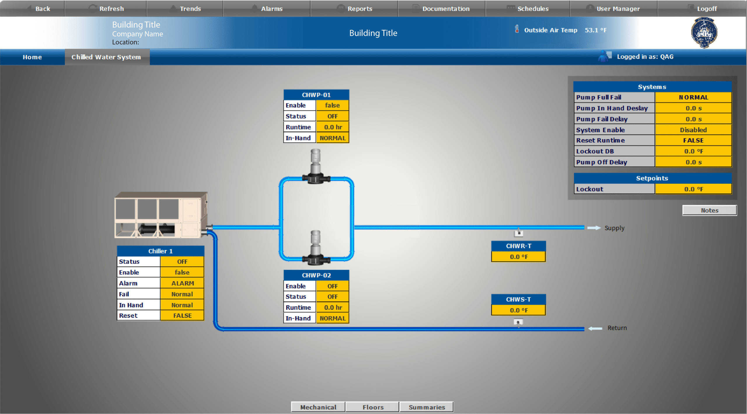
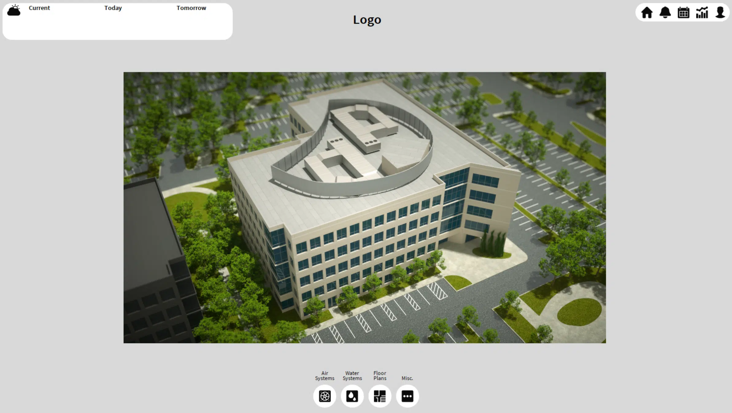
QA Graphics is a full-service outsourcing company, providing custom HVAC system graphics, as well as design services for interactive platforms. We help clients visualize their needs and simply their lives. Our talented designers come form a wide range of backgrounds to provide the personal attention and expertise needed to being our clients’ ideas to life. Our partnerships with industry leaders like Johnson Controls and Schneider Electric ensure high-quality BAS graphics solutions.
Why Choose Us for Your BAS Graphics Needs?

Reduced Lead Time
Shorten the time it takes to deliver BAS graphics by outsourcing to our dedicated graphical team

Use The Experts
Have your team focus on programming and let us take care of the BAS graphics

Efficient Graphics
Create a standard within your company to maximize a creative look and feel for your end customer

Cost Savings
Increase your ROI by saving your technicians time and your budget by reducing graphical software when you outsource with us
Who We Are
We are a full-service outsourcing company, providing custom HVAC system graphics and BAS graphics design services for interactive platforms. Helping clients visualize their needs and simplify their lives, our talented designers come from a wide range of backgrounds to provide the personal attention and expertise needed to bring our clients’ ideas to life.
All of our work is completed in-house, with a team comprised of both creative and technical staff, including graphic designers, 3D designers, developers, programmers, architects, and mechanical engineers, to ensure we meet our clients’ diverse needs. We are a fun and creative group who takes pride in our Midwestern values and affordable prices.


Graphics for Over 95% of BAS Systems
Our design team includes trained mechanical engineers that can create system graphics for almost all building automation systems including:
- JCI: Metasys UI
- JCI: Facility Explorer (FX)
- JCI: Metasys GGT
- Tridium: Niagara AX
- Tridium: Niagara 4
- Schneider: Struxureware
- And many more
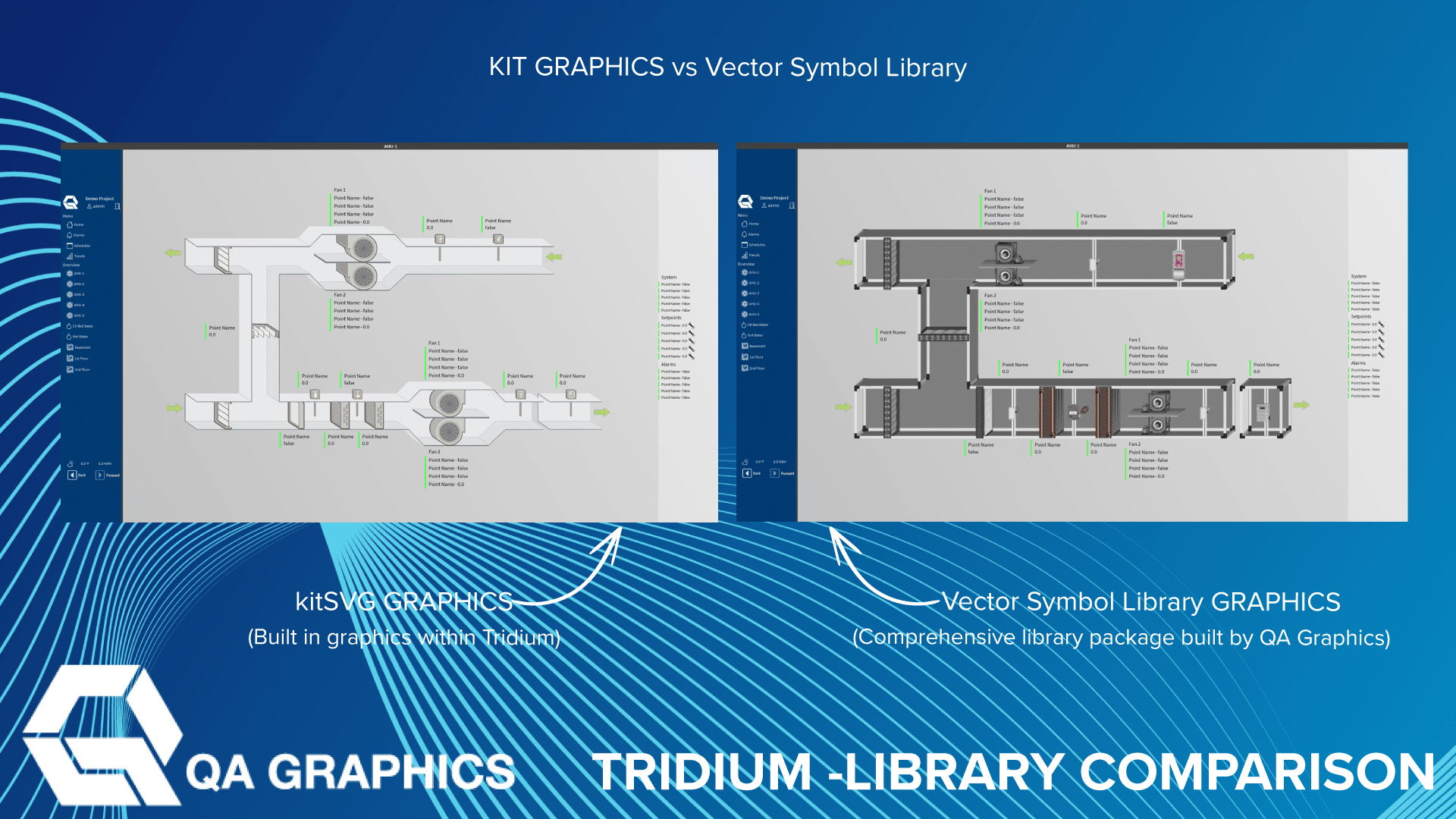
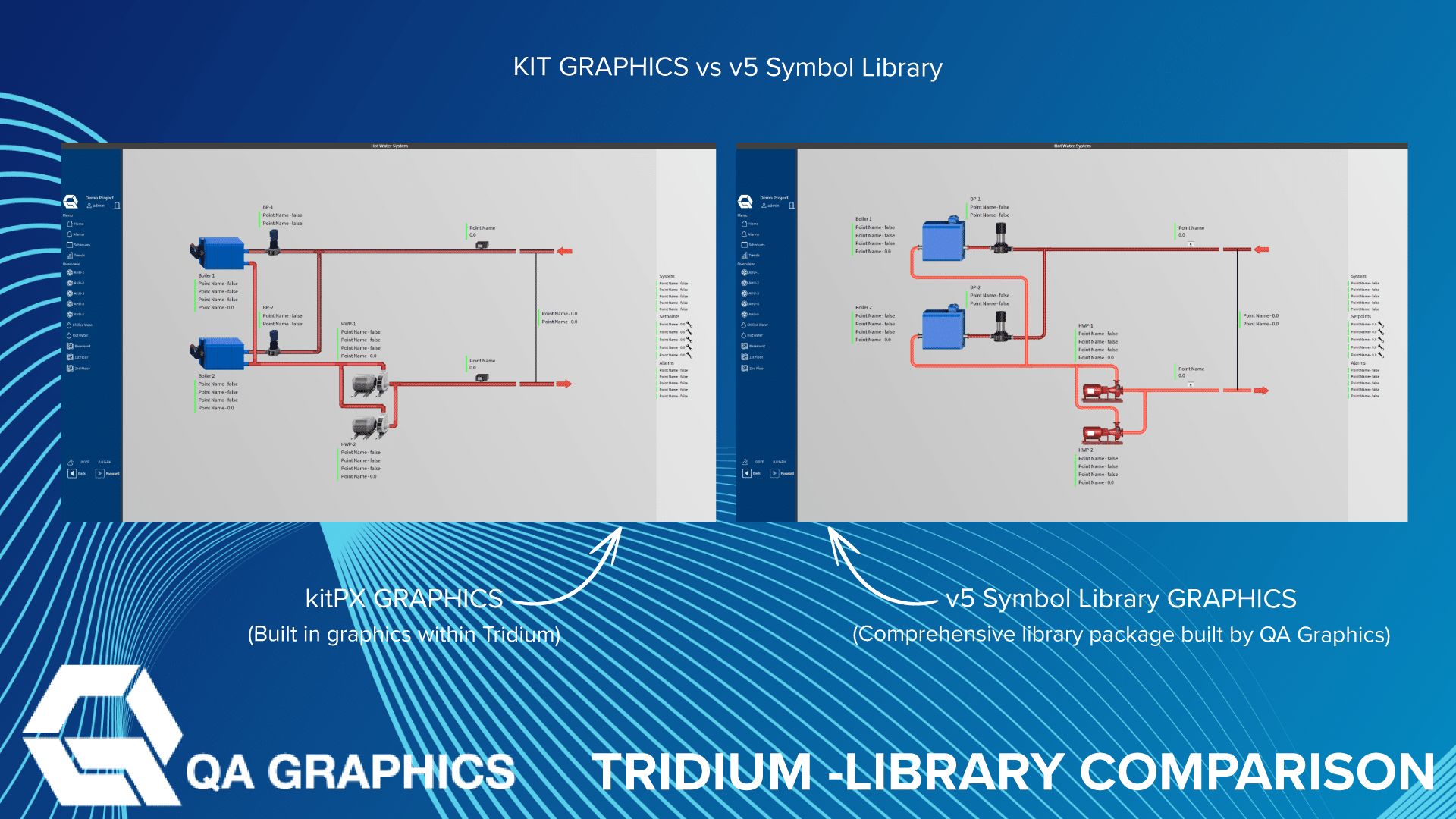
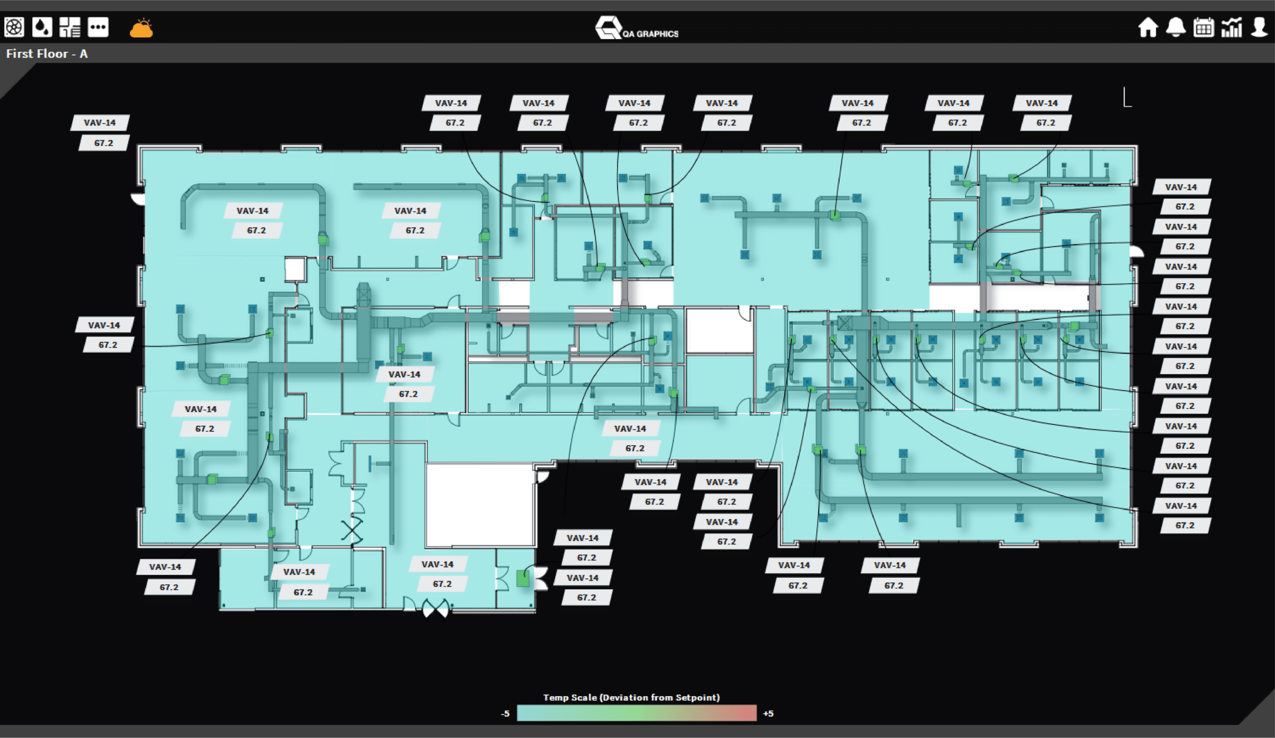
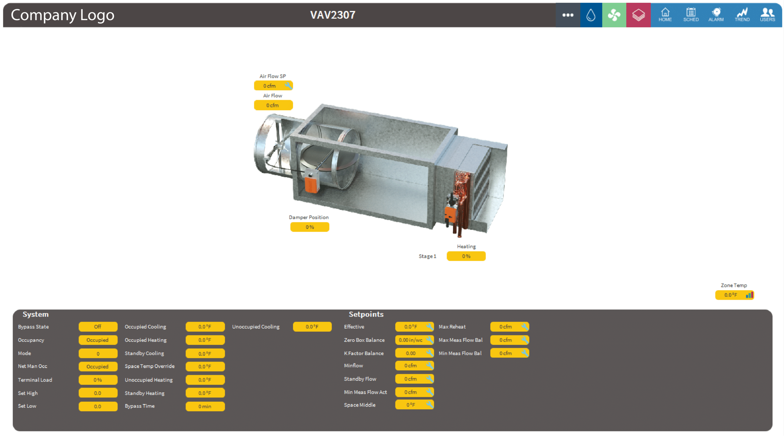
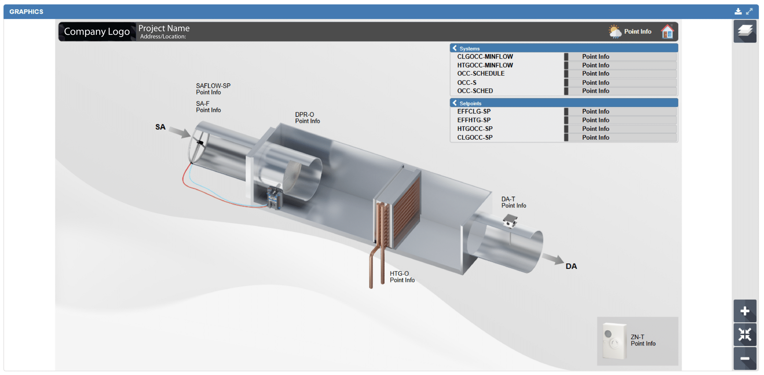
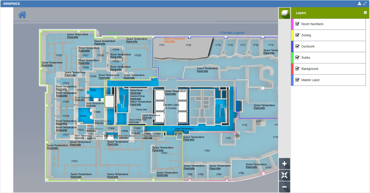
Niagara System Graphics
QA Graphics provides system graphic development for all versions of Niagara 4, including Niagara Reflow.
We can develop BAS graphics using the existing Niagara symbol libraries or provide custom BAS graphics solutions. QA Graphics enhanced symbol libraries both come with .jar files that have the ability to be seamlessly used inside of all Niagara software.
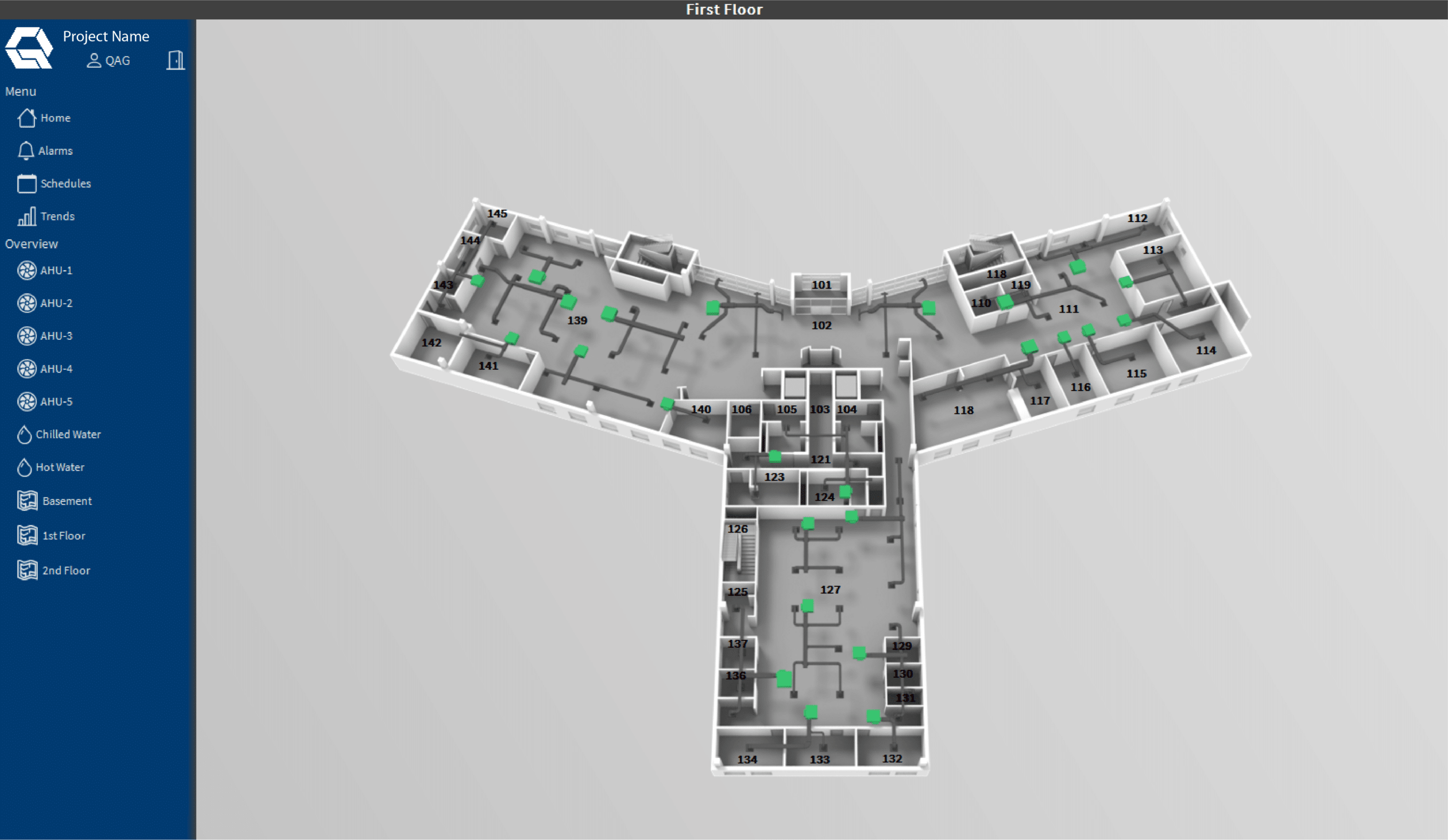
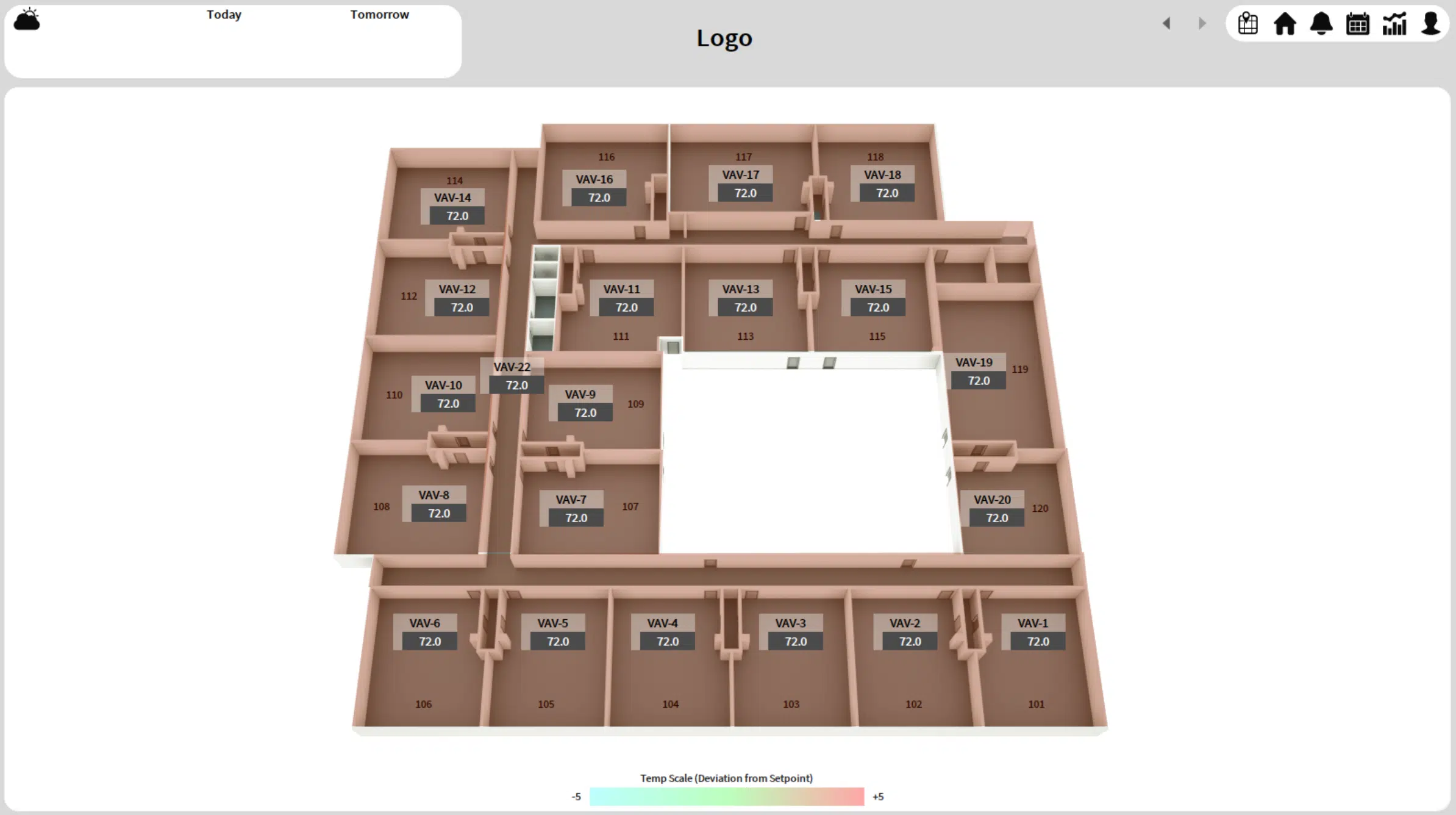
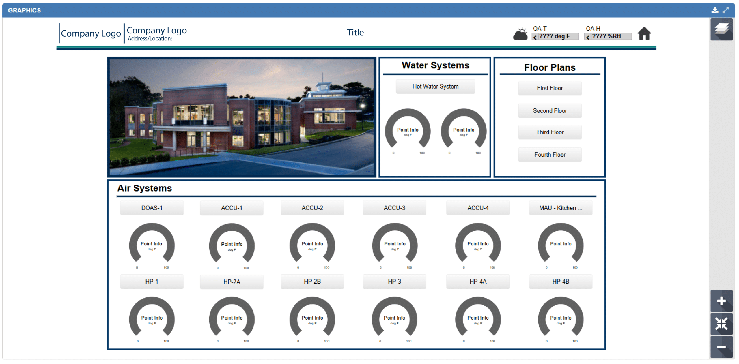
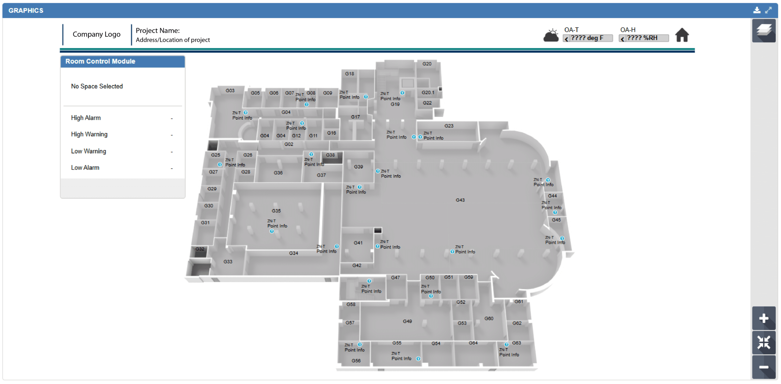
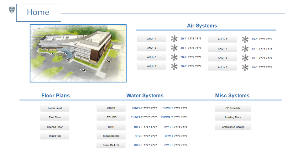
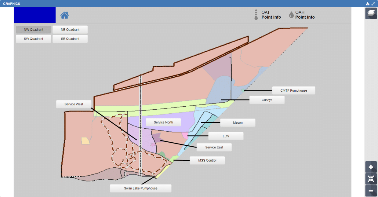
QA Graphics full turnkey solution includes all of the site’s equipment graphics, floor plans, navigation and point mapping. The work can be completed on a live station via VPN, or offline with a station backup.
We provide an assortment of pre-designed Niagara 4 templates that have been thoughtfully created to suit various company designs. You can now enhance your project’s appearance effortlessly by choosing the style that most accurately represents your brand identity.
We understand that certain businesses may have unique aesthetic needs or branding standards. If you’re unable to locate a pre-designed option that matches your expectations, there’s no need for concern! Our skilled team is committed to developing tailored styles just for your company and/or your clients.

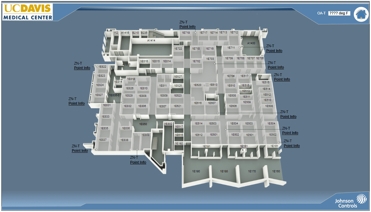
JCI
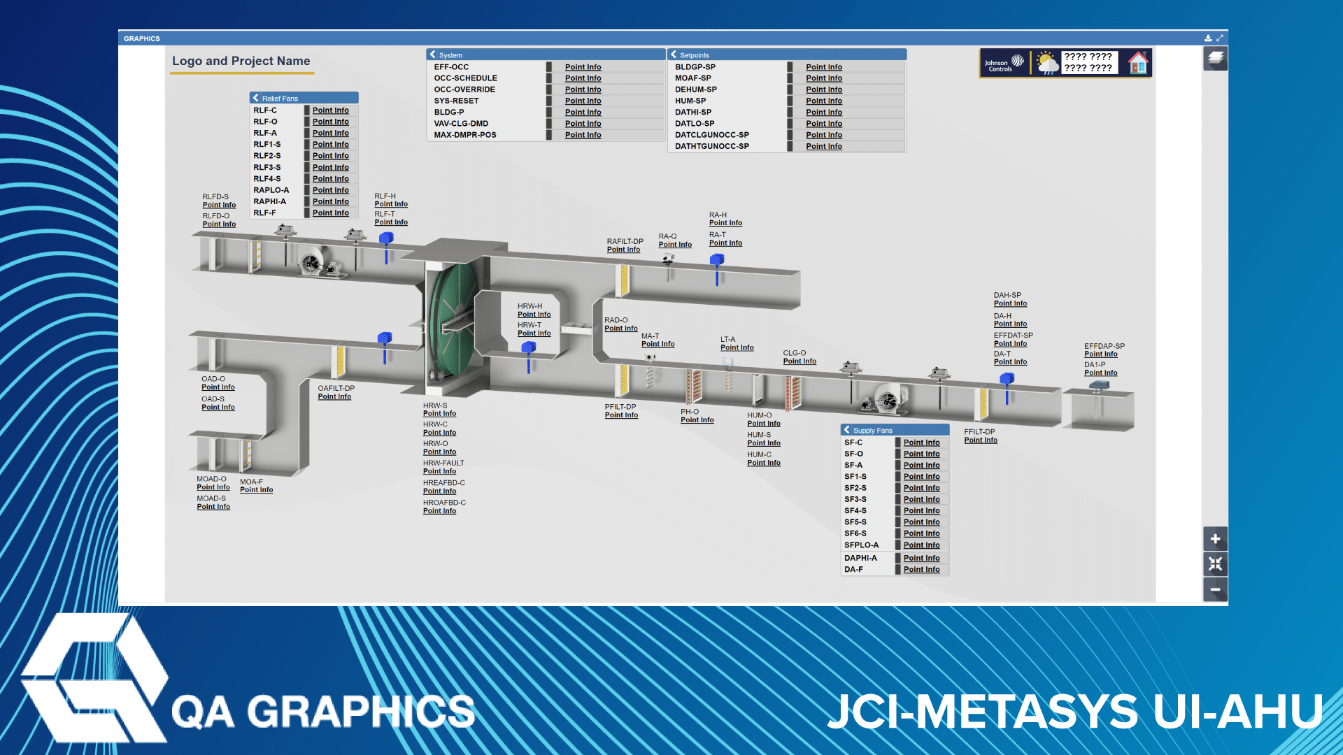
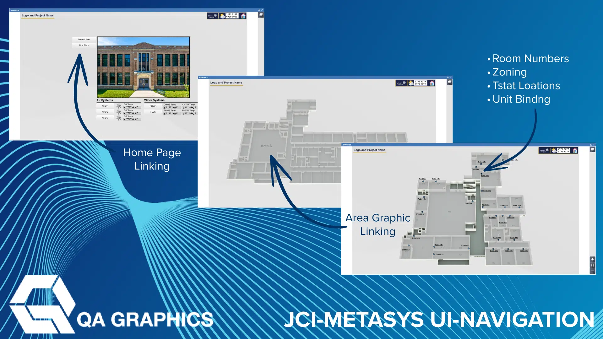
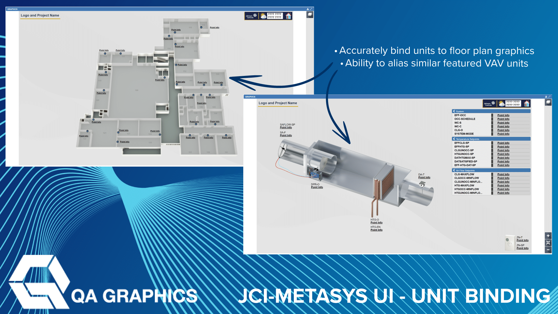
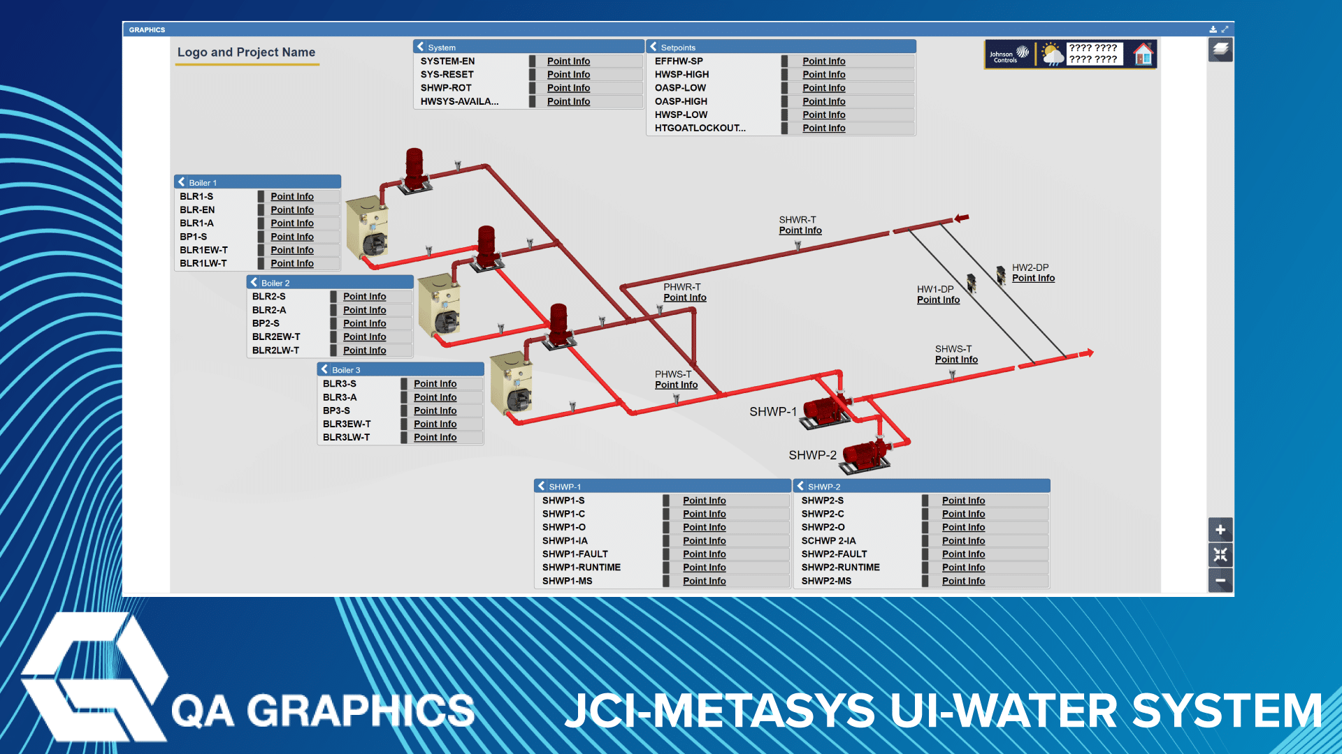
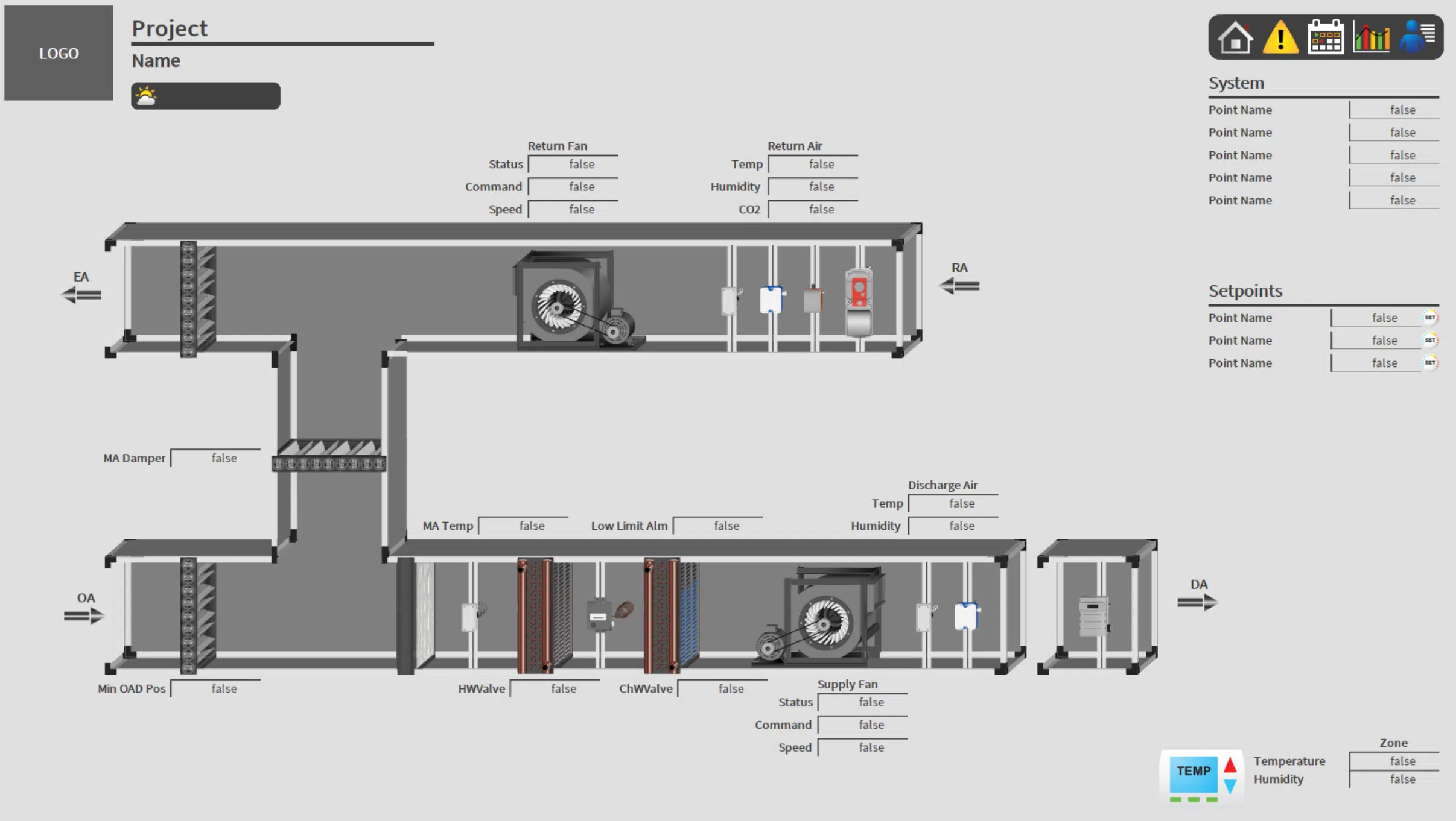
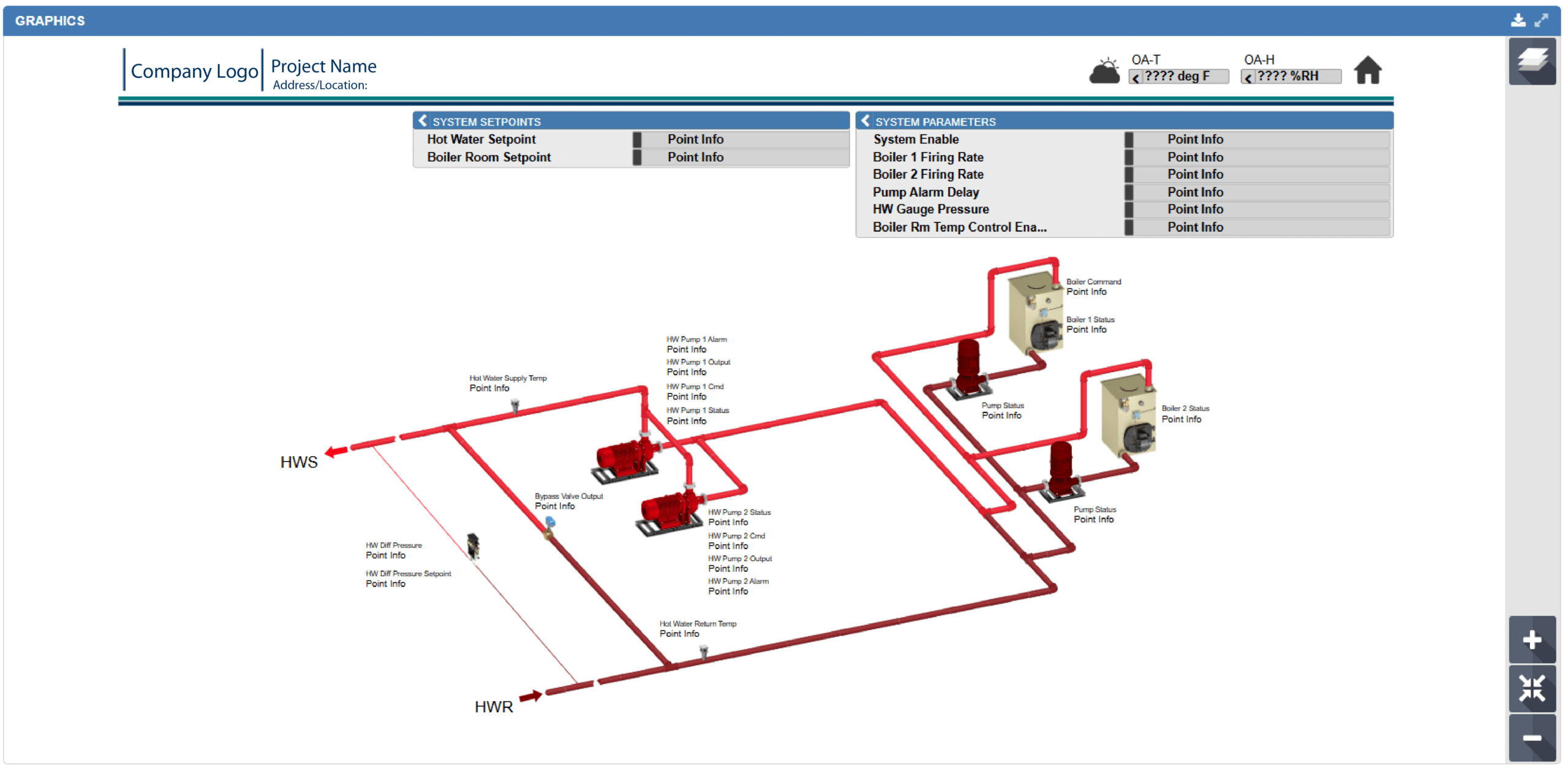
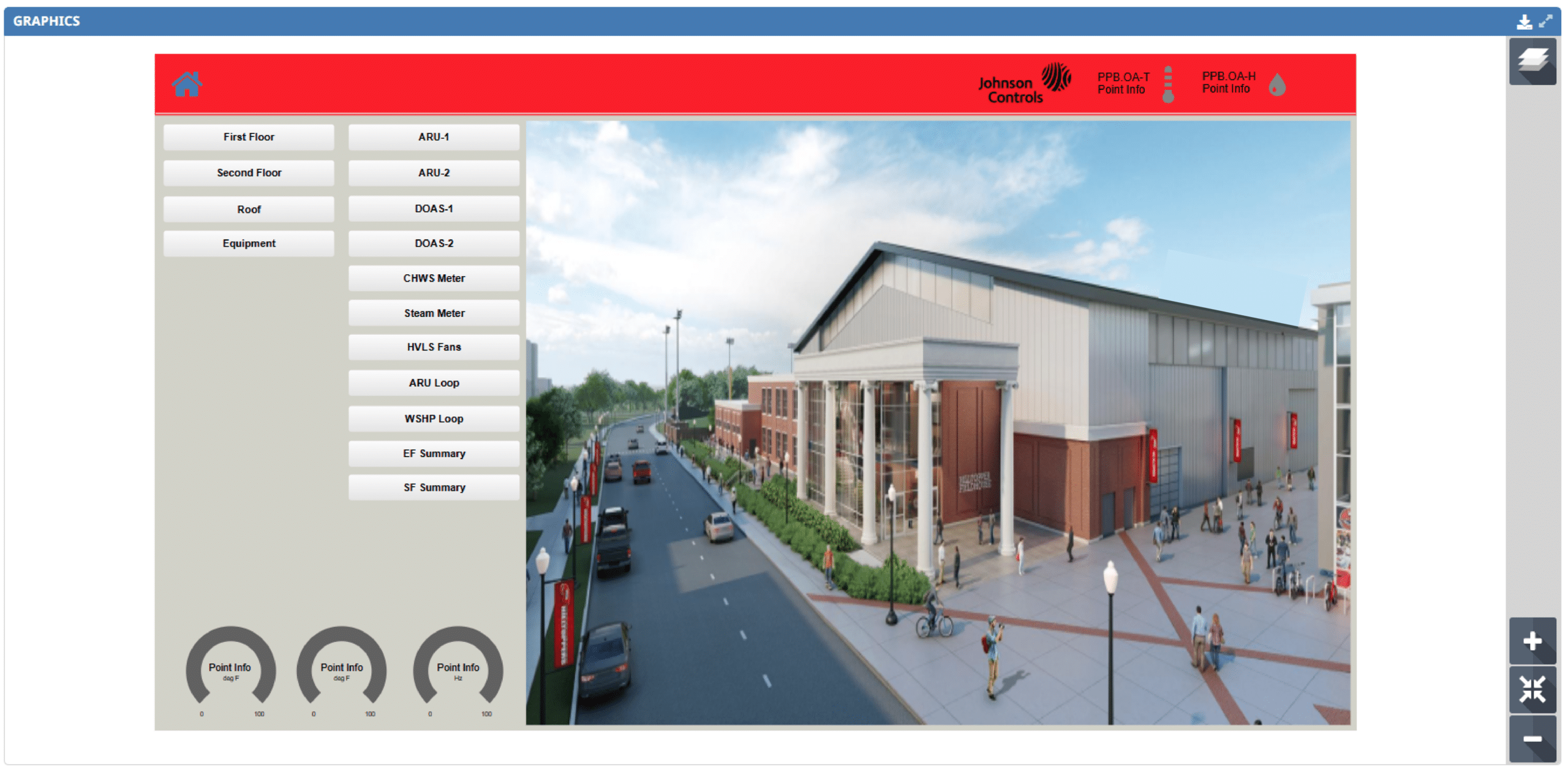
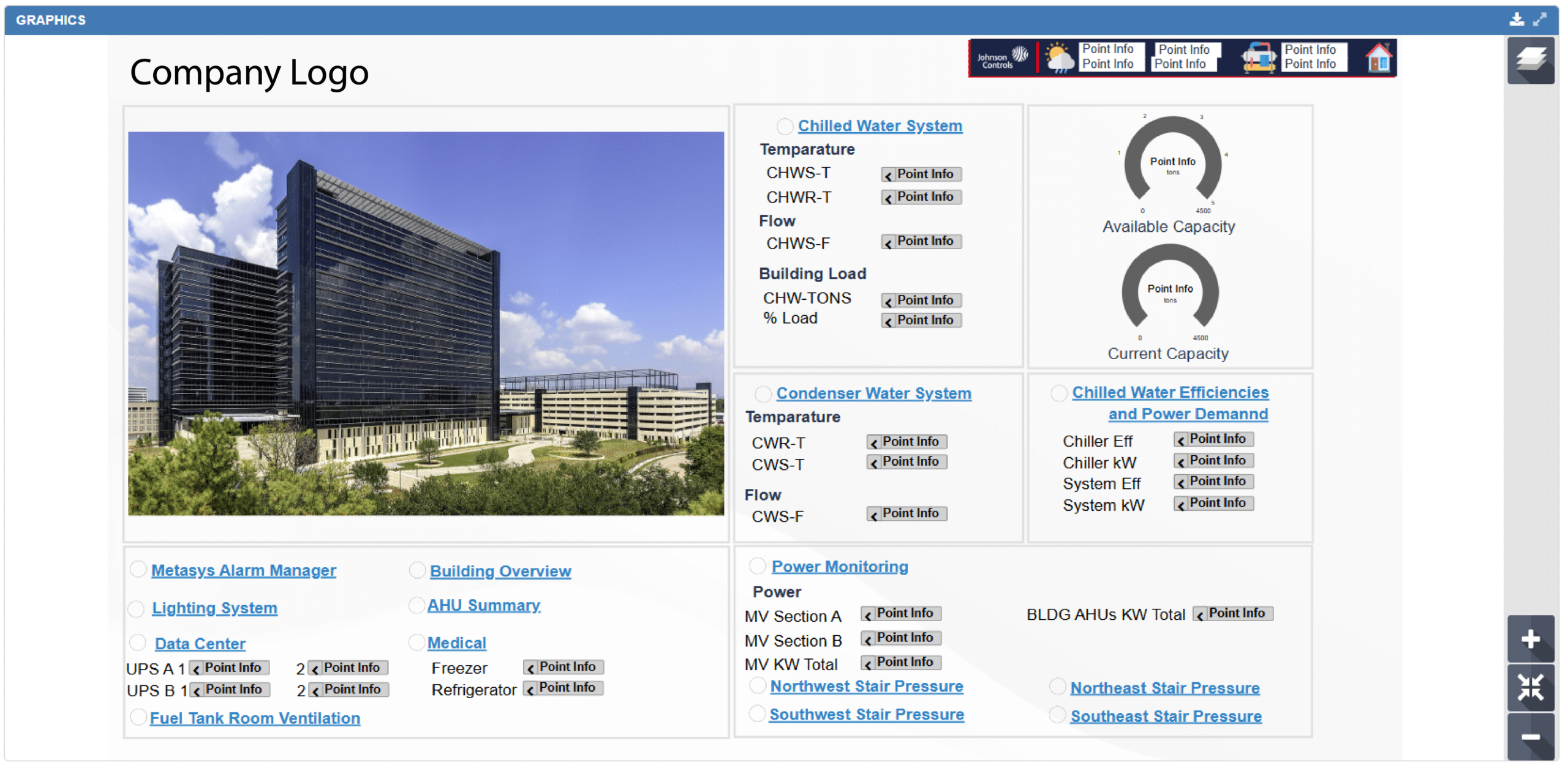
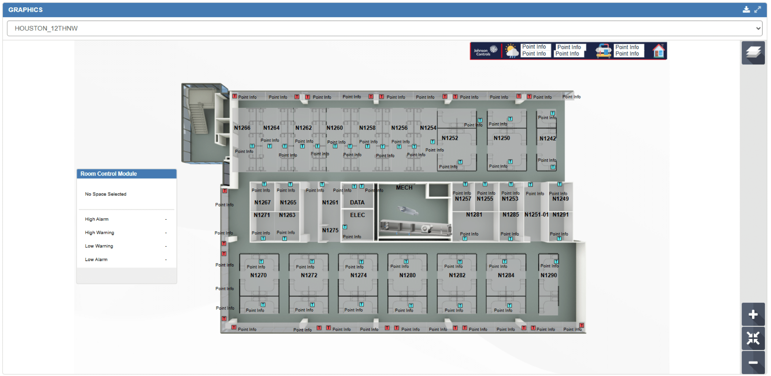
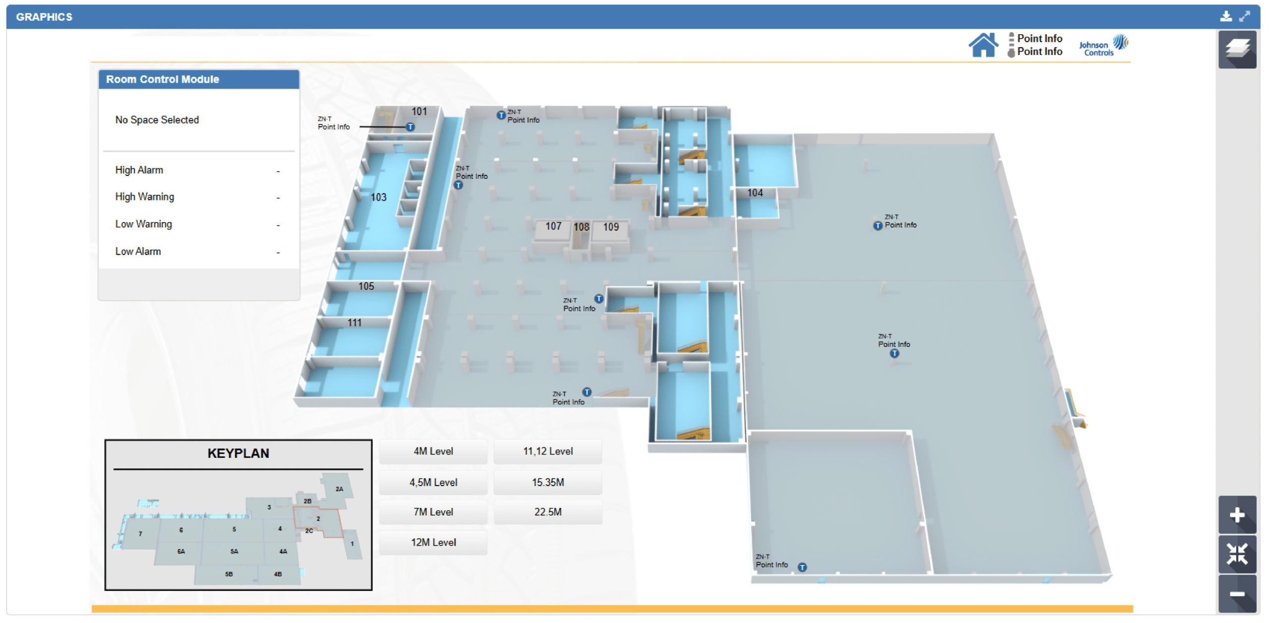
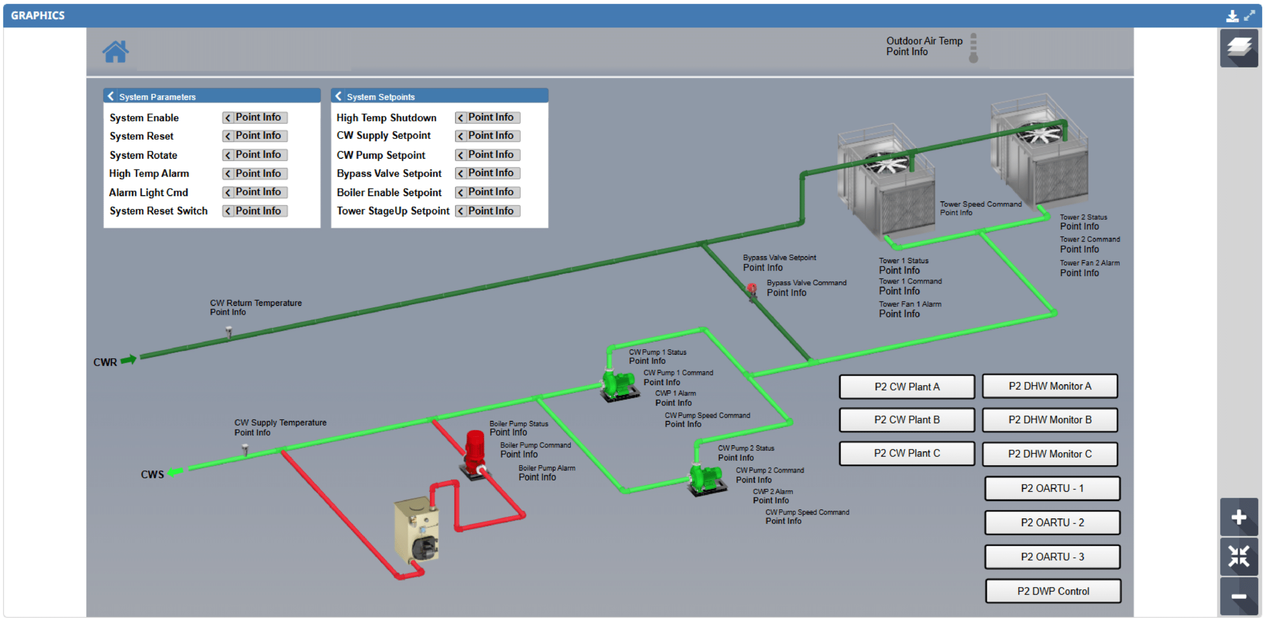
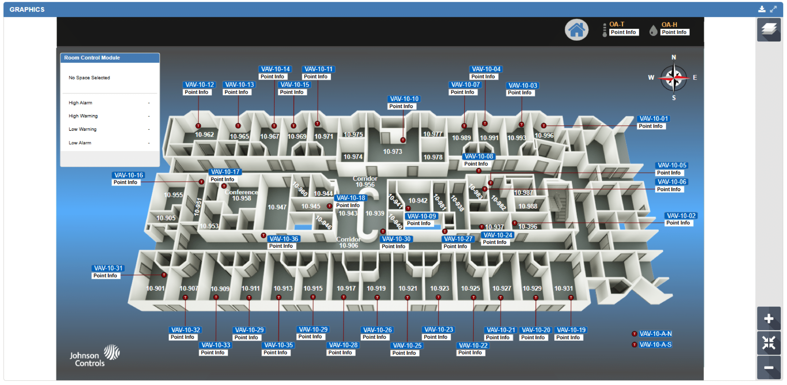
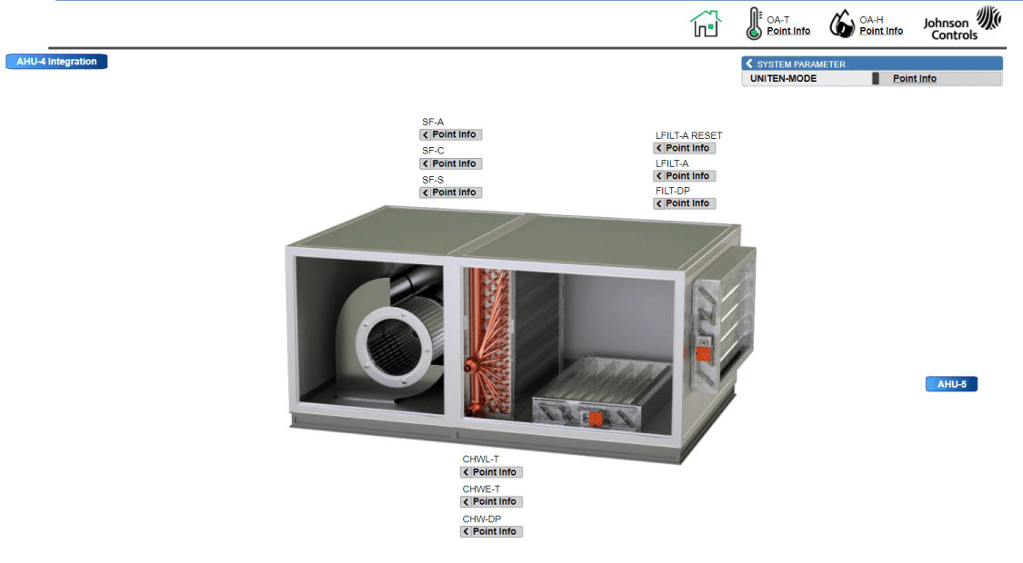
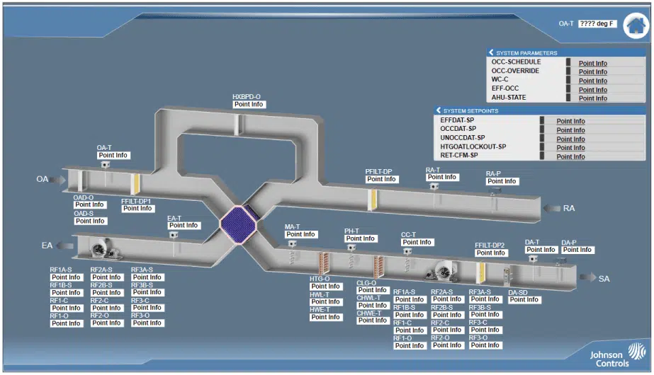
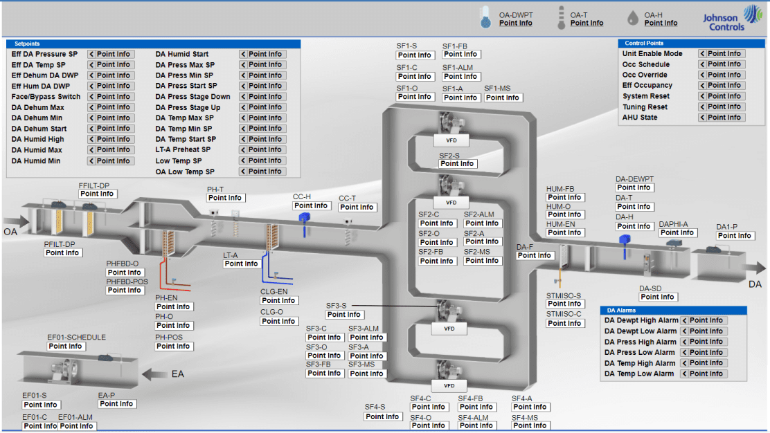
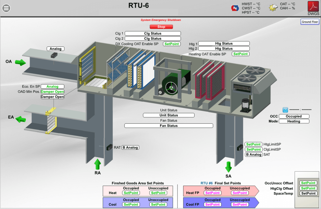
QA Graphics is the industry-leading provider of comprehensive BAS graphics services for Johnson Controls, Inc. projects. Johnson Controls has named QA Graphics as one of only two pre-qualified subcontractors with the ability to perform graphical work. Our skilled mechanical engineers can create the best system graphics for Metasys UI and Graphics+. Everything is done in-house, here in the United States, with nothing outsourced overseas.
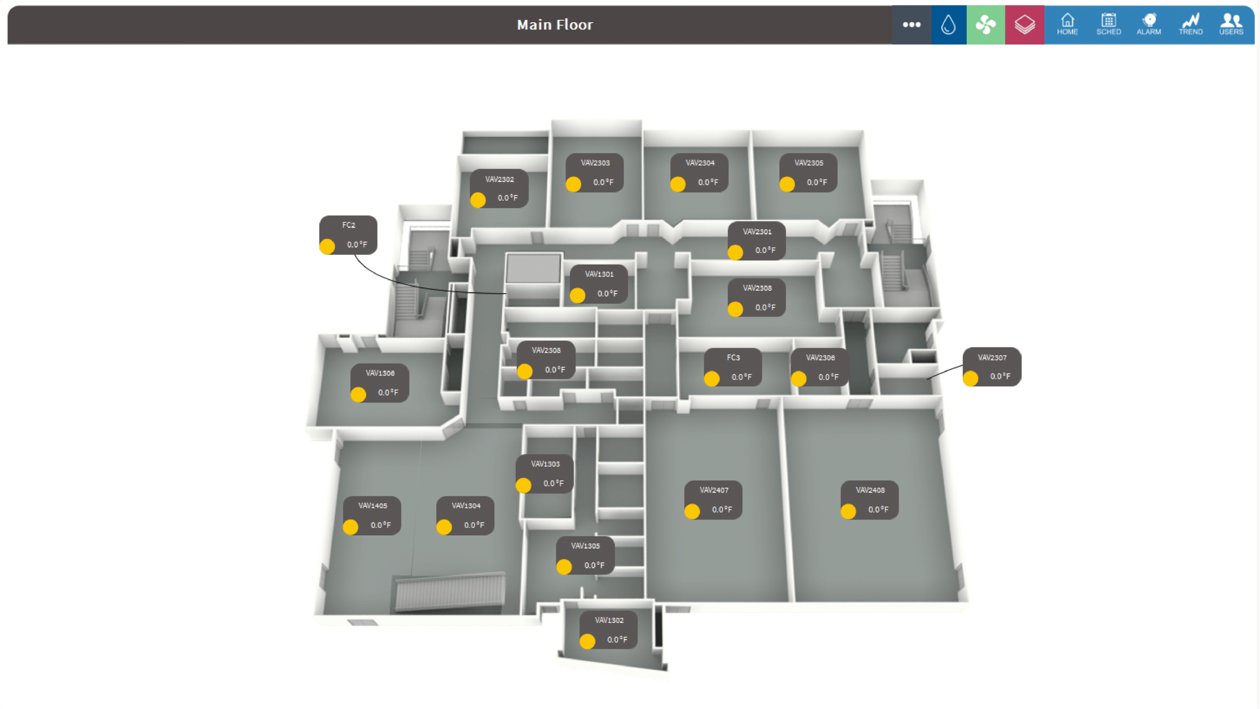
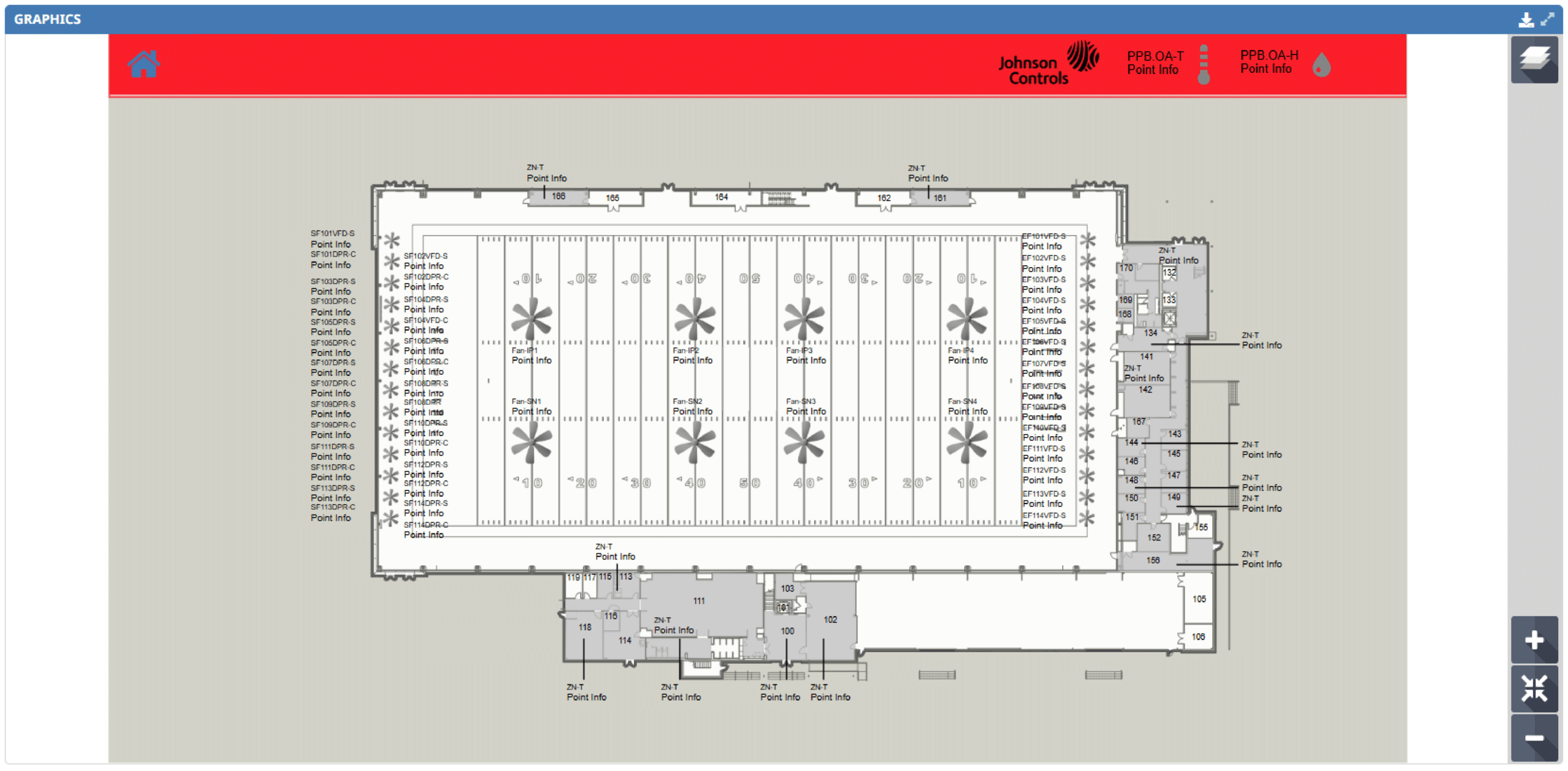
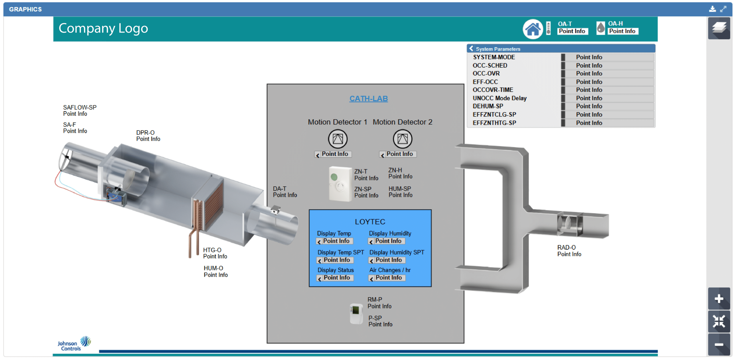
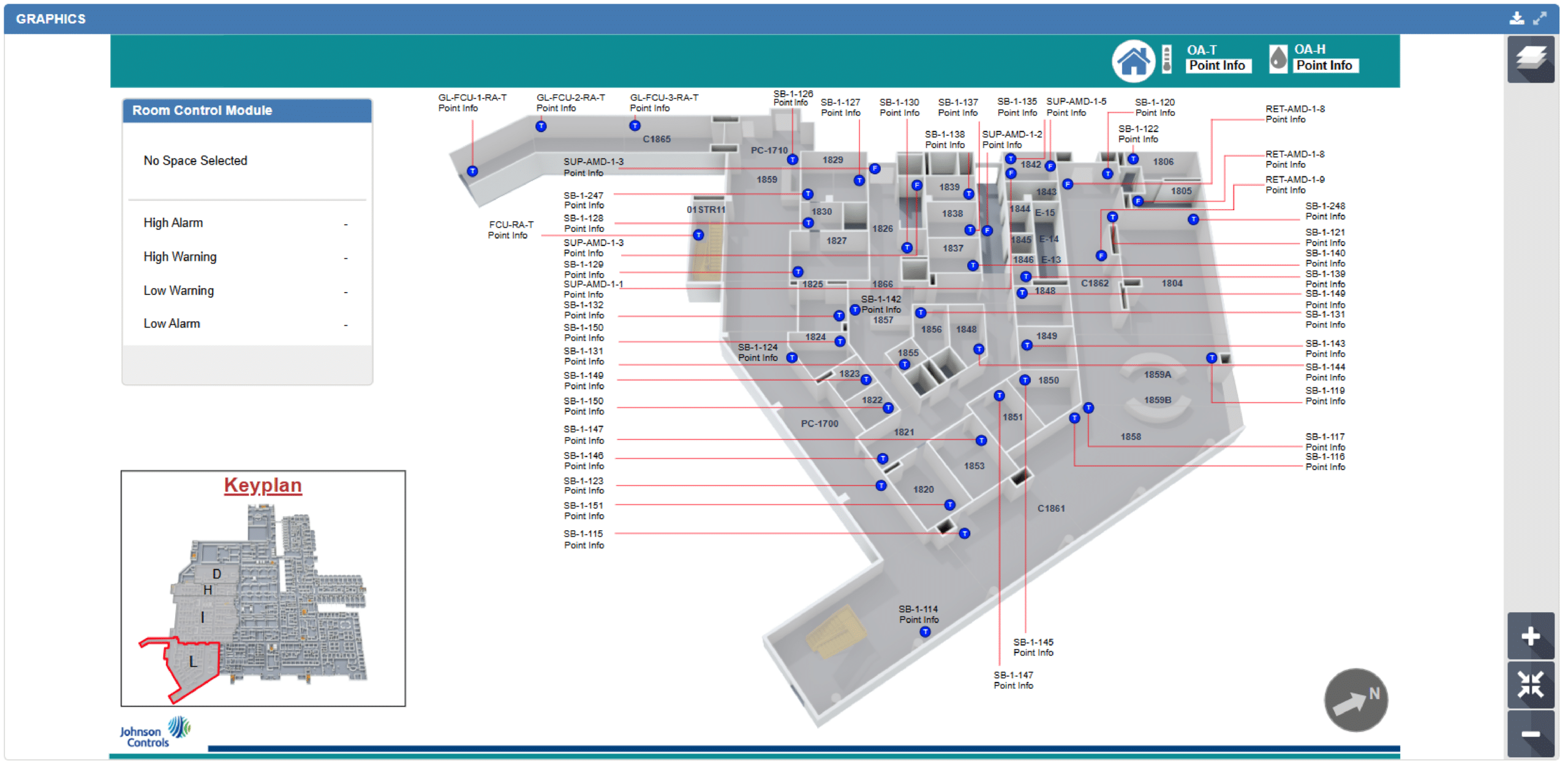
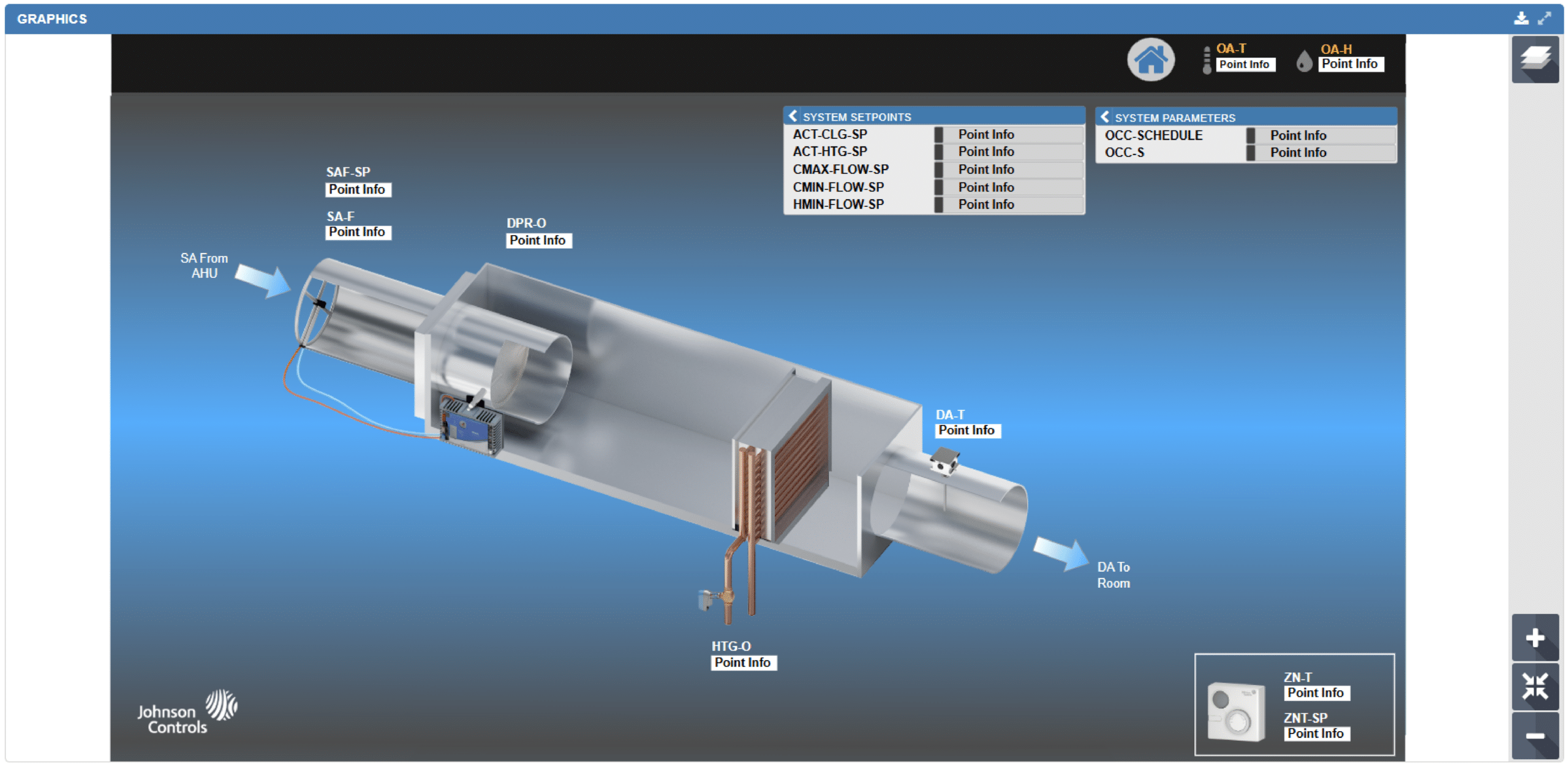
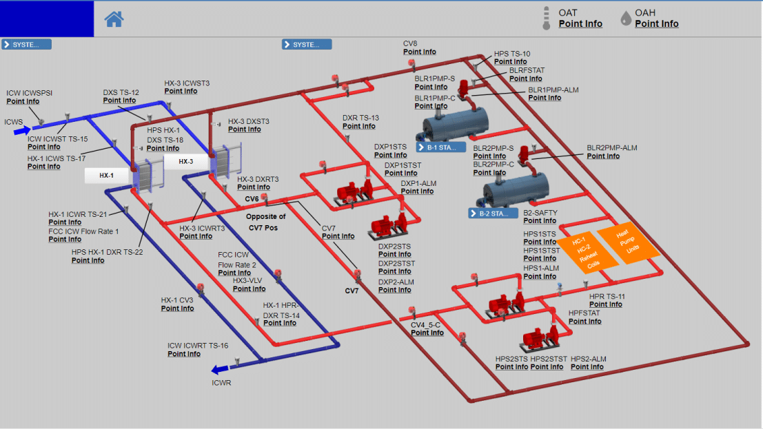
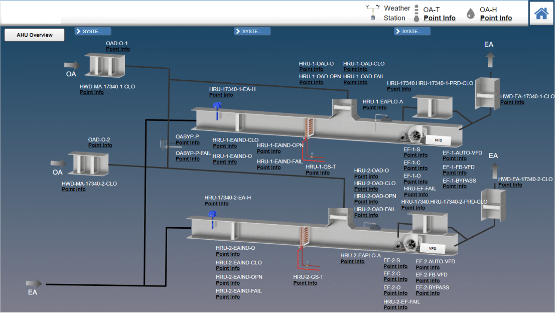
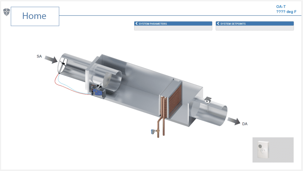
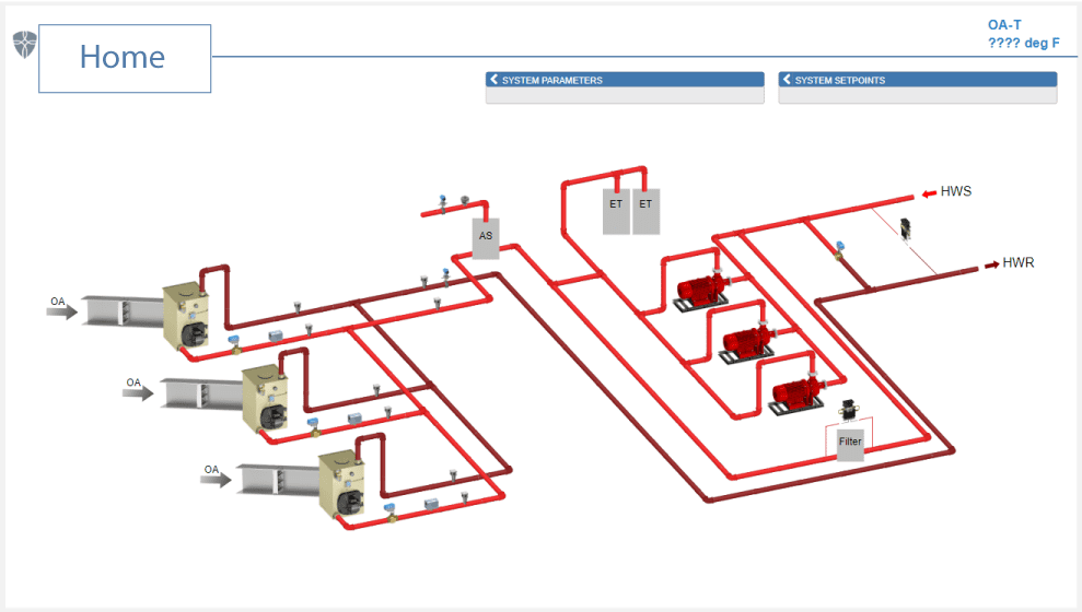
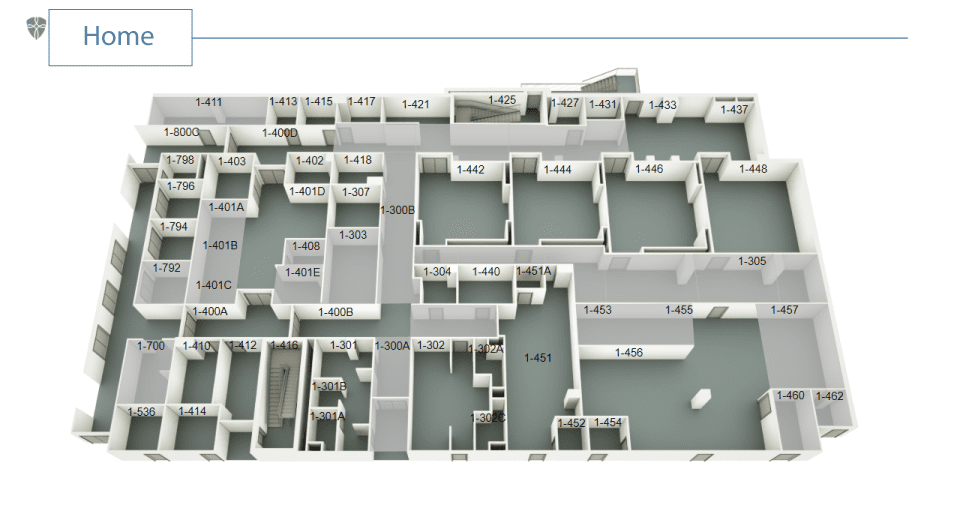
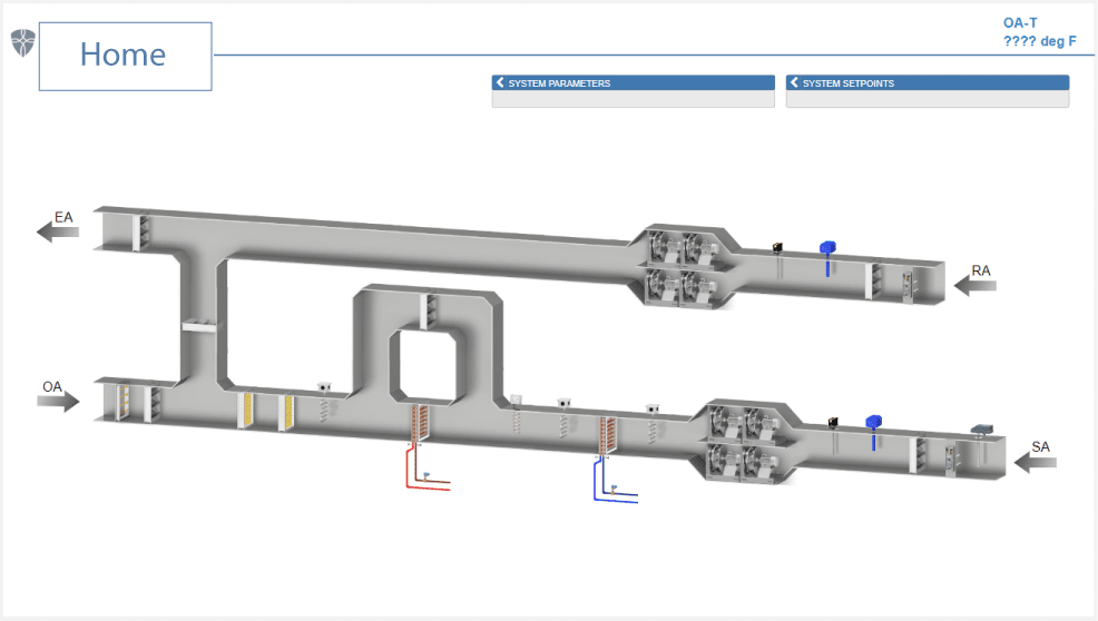
Our team is trained in creating all Metasys UI (MUI) graphics, as well as the spaces and definitions that drive the front-end graphics. MUI is an efficient software that allows the user to provide photo-realistic images of equipment, systems, and floor plans. Our team provides consistent, high-end graphics for a customer from start to finish with a submittal process to ensure that each customer is provided exactly what they need on a project-by-project basis.
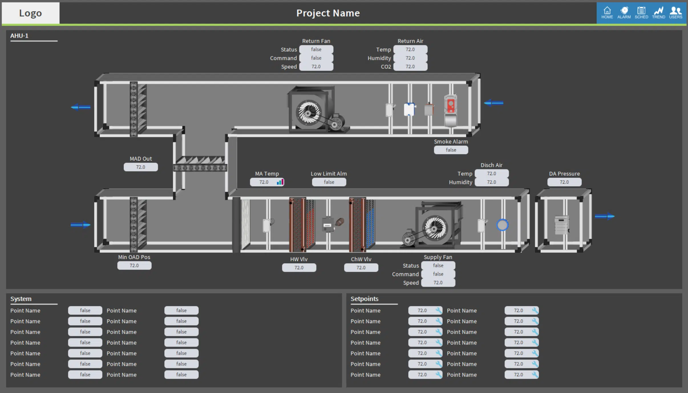
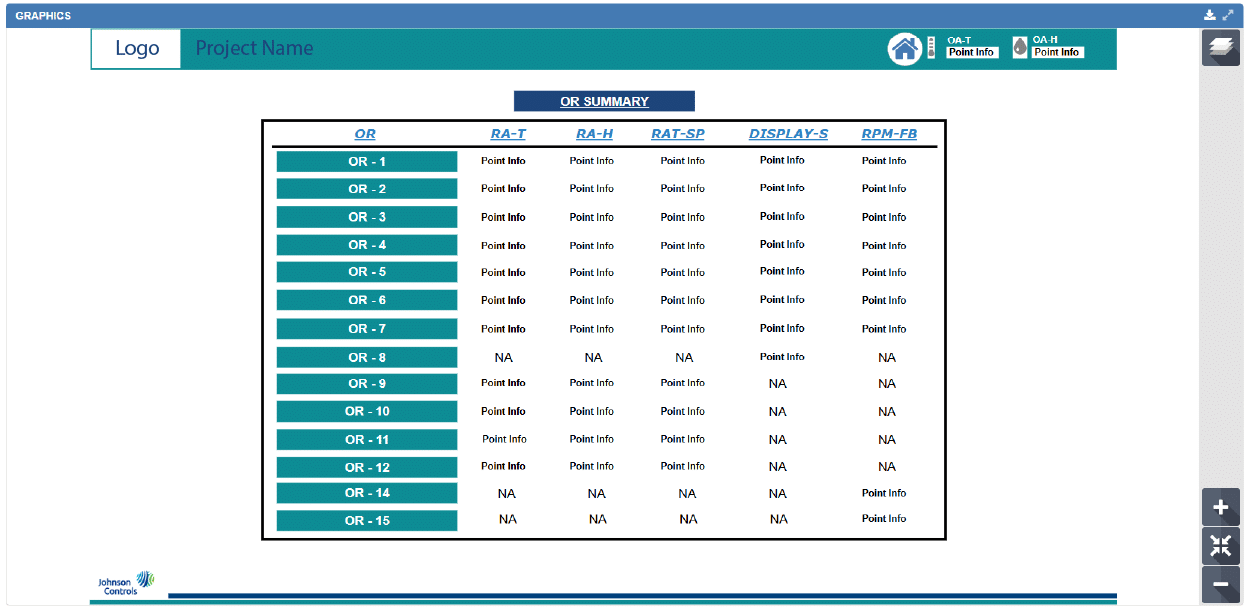
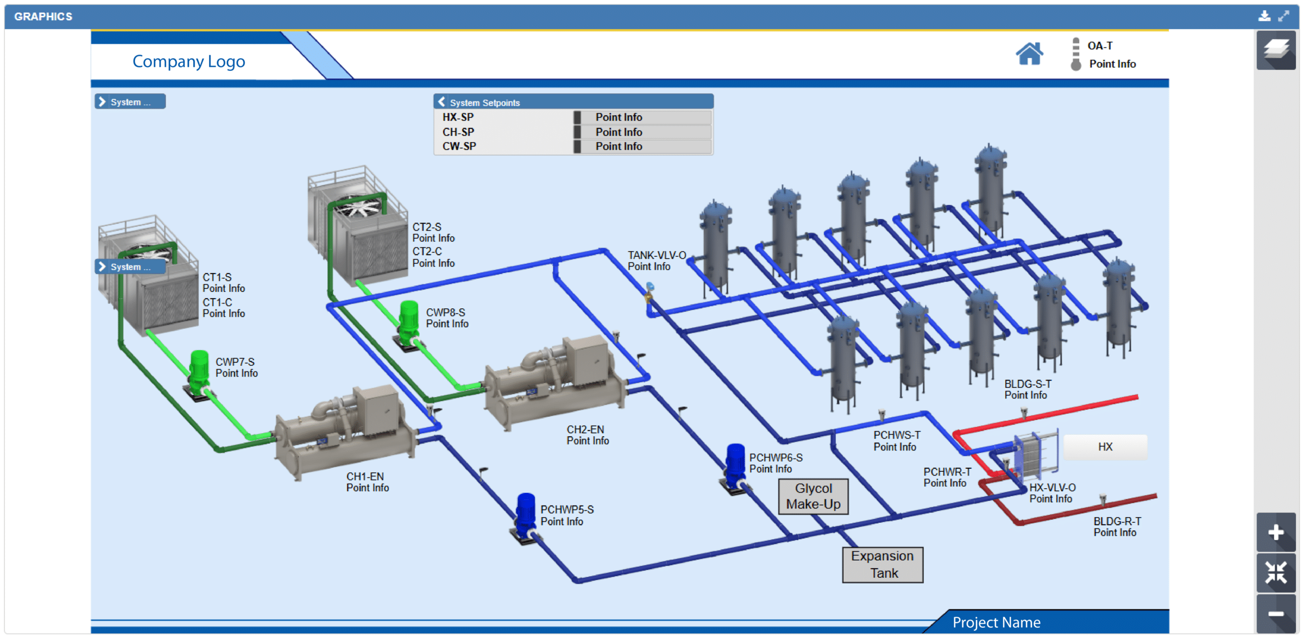
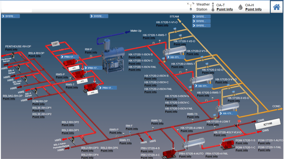
Graphics+ graphics are designed with the Graphic Generation Tool (GGT) – a powerful diagramming tool that helps designers create compelling representations and bind them to data objects.
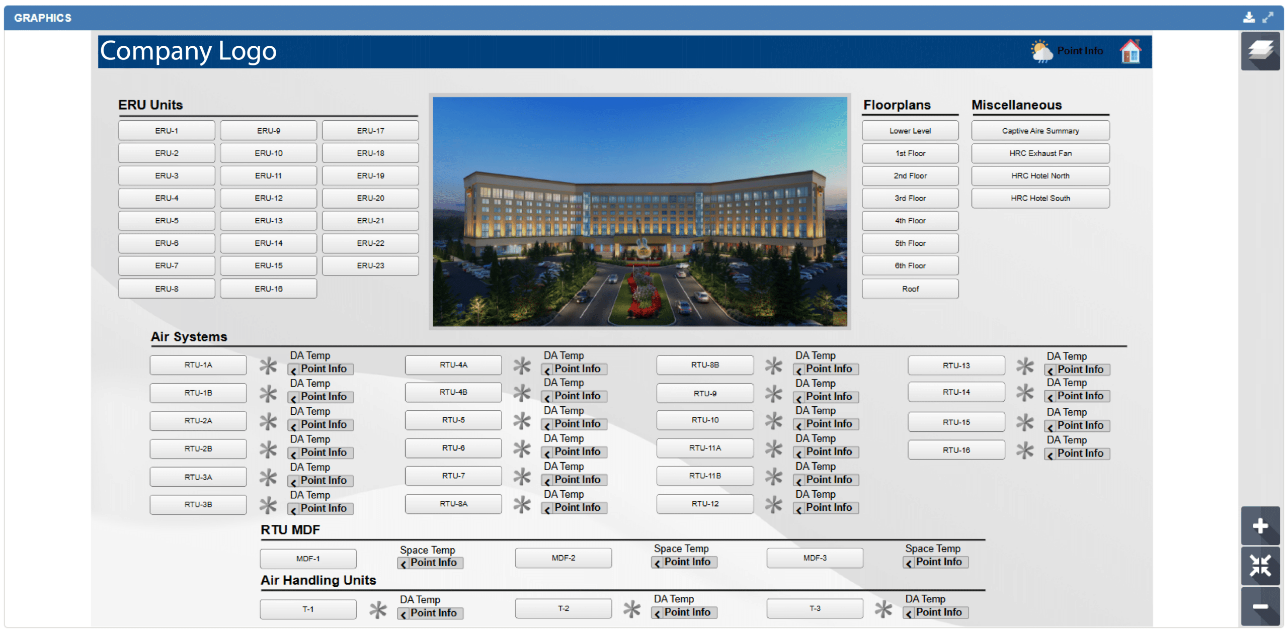


We offer a range of pre-made Johnson Controls MUI templates, meticulously designed to fit different corporate aesthetics. With just a few clicks, you can elevate the visual appeal of your project by selecting a design that best aligns with your brand image.
Recognizing that some companies possess distinctive visual requirements or branding guidelines, we encourage you not to worry if you can’t find a suitable pre-made option. Our talented team is dedicated to crafting custom designs specifically for your organization or your clientele.

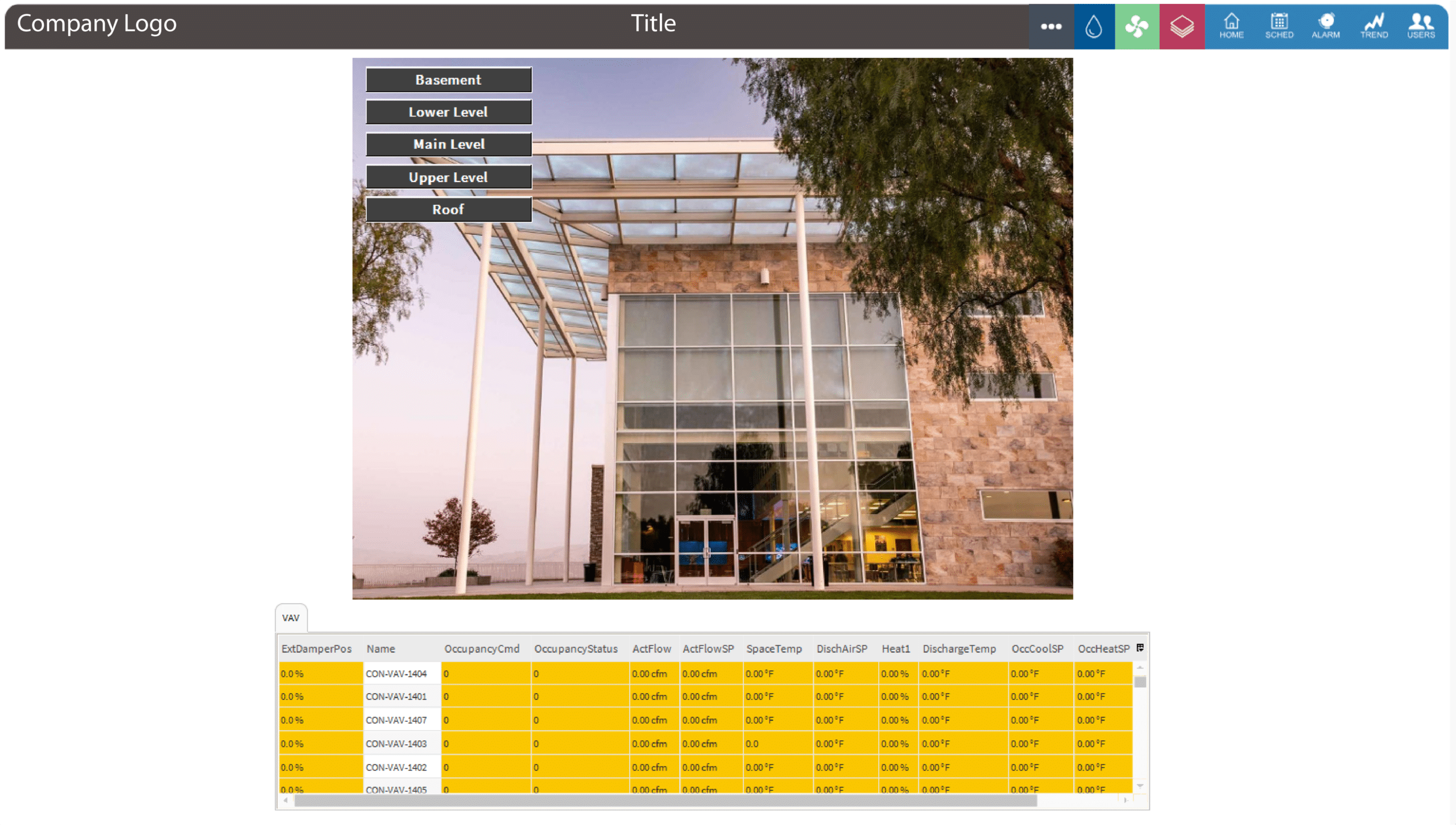
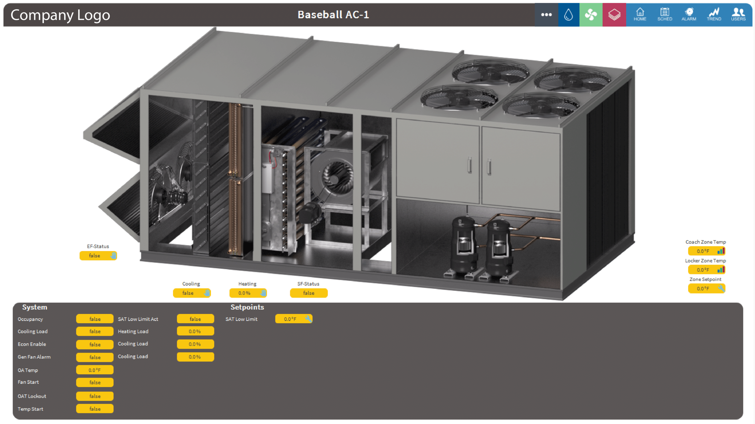
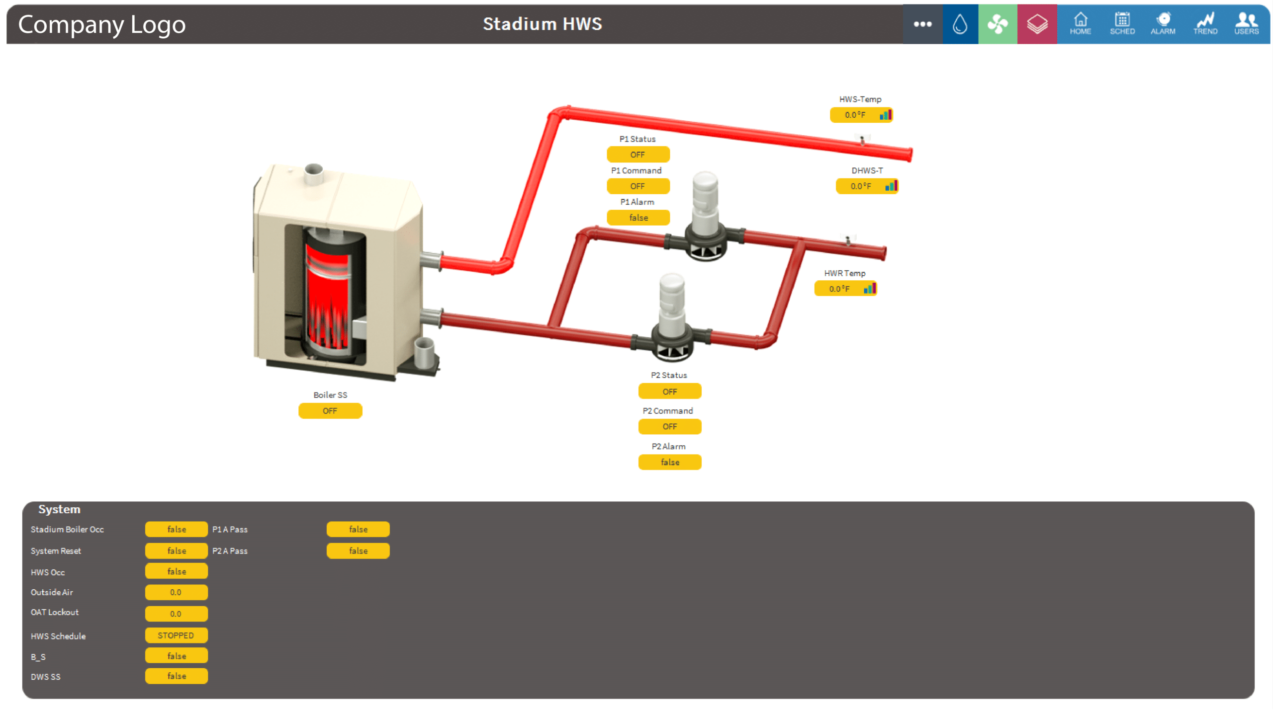
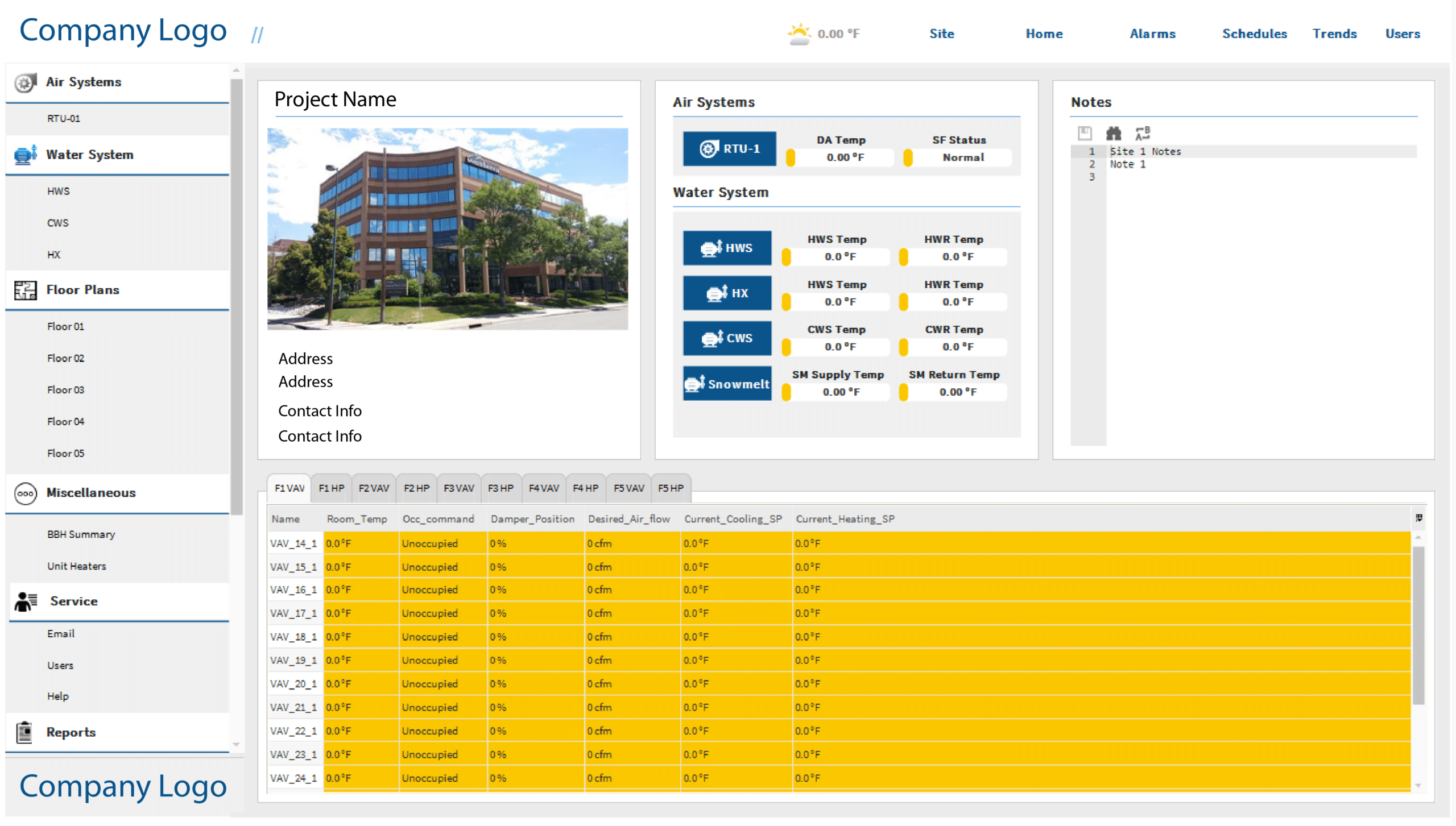
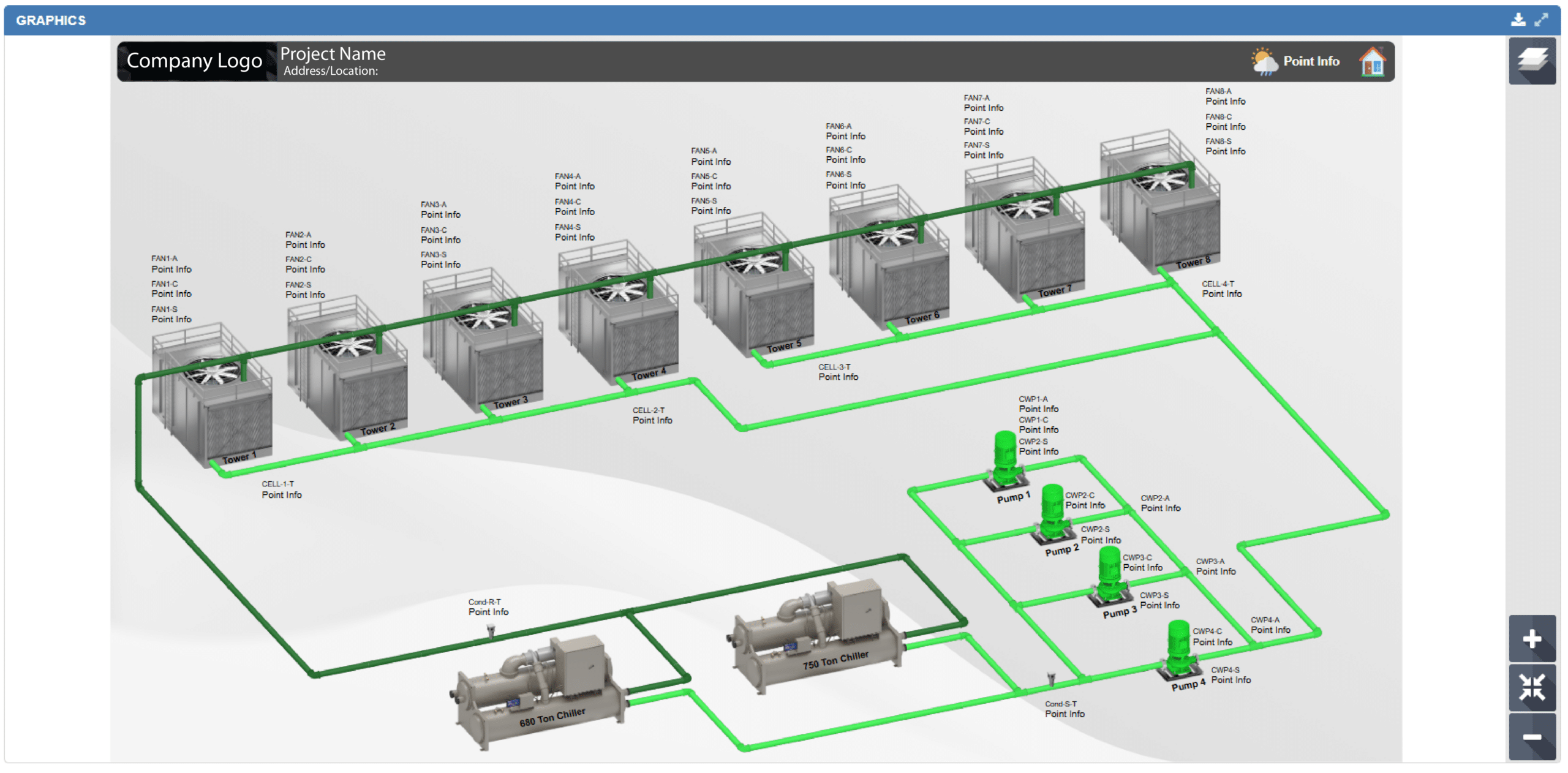
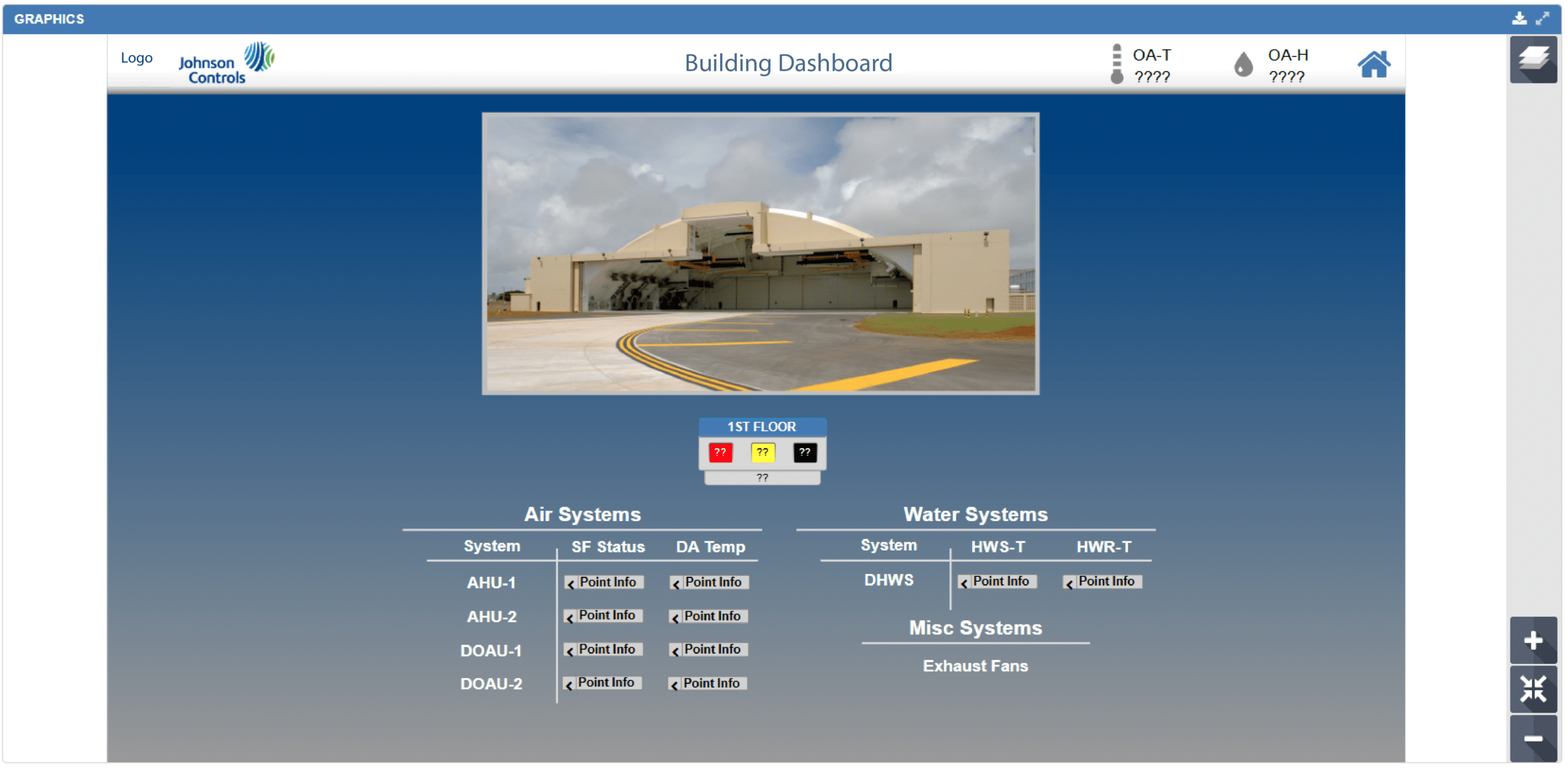
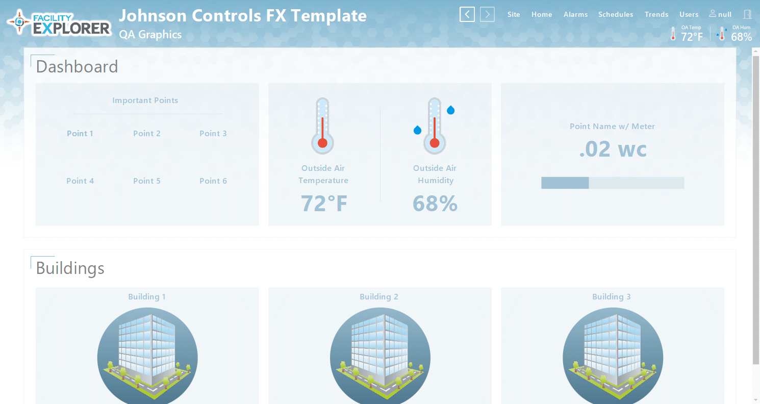
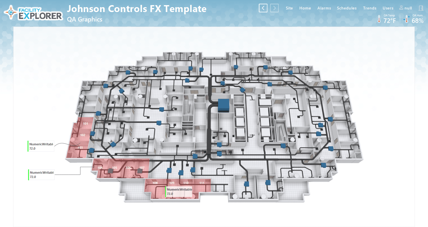
JCI-Facility Explorer
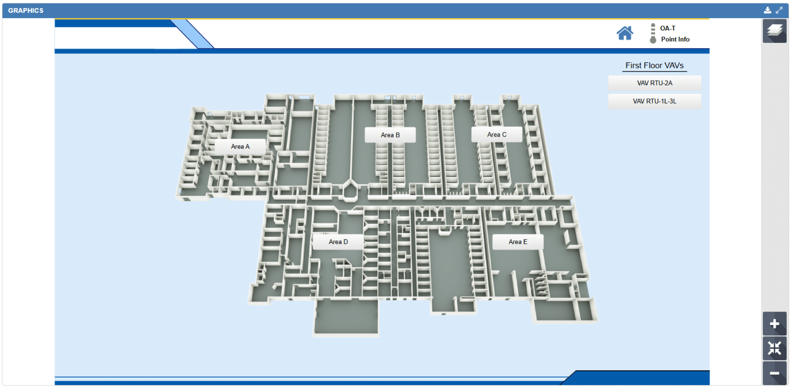
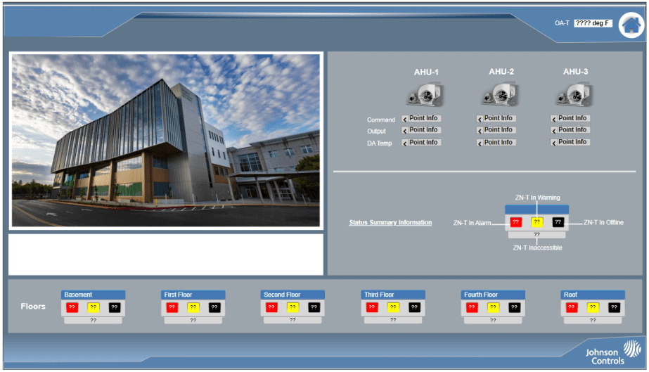
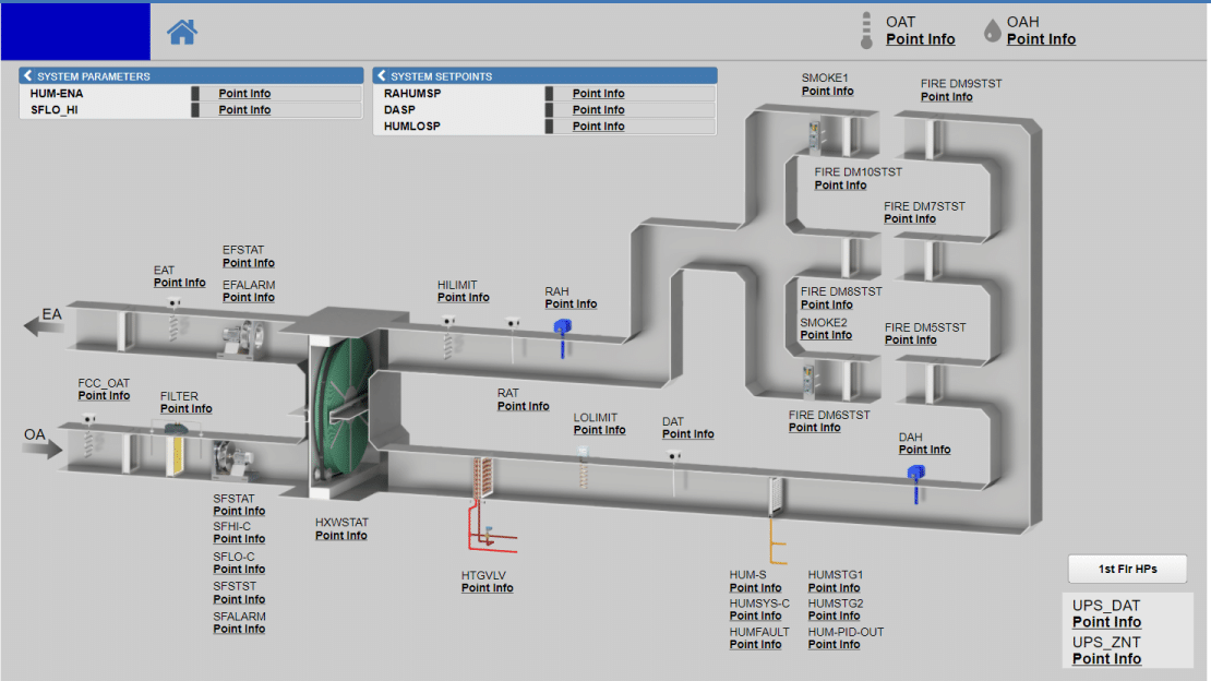
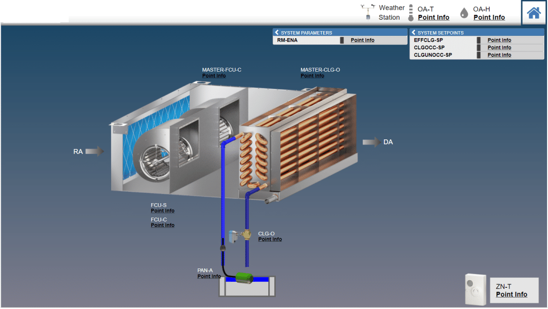
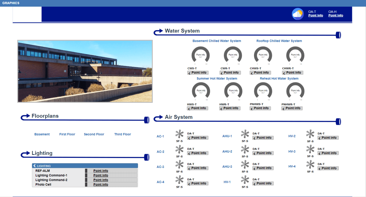
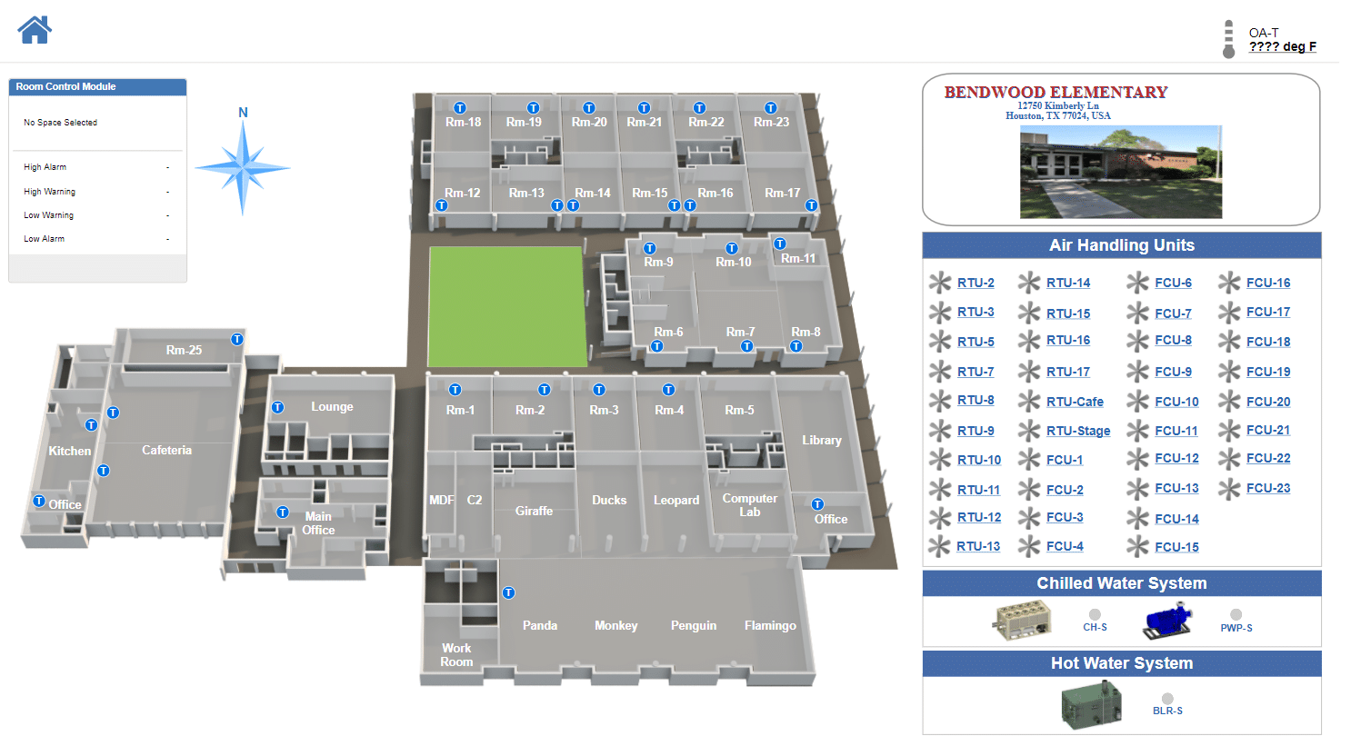
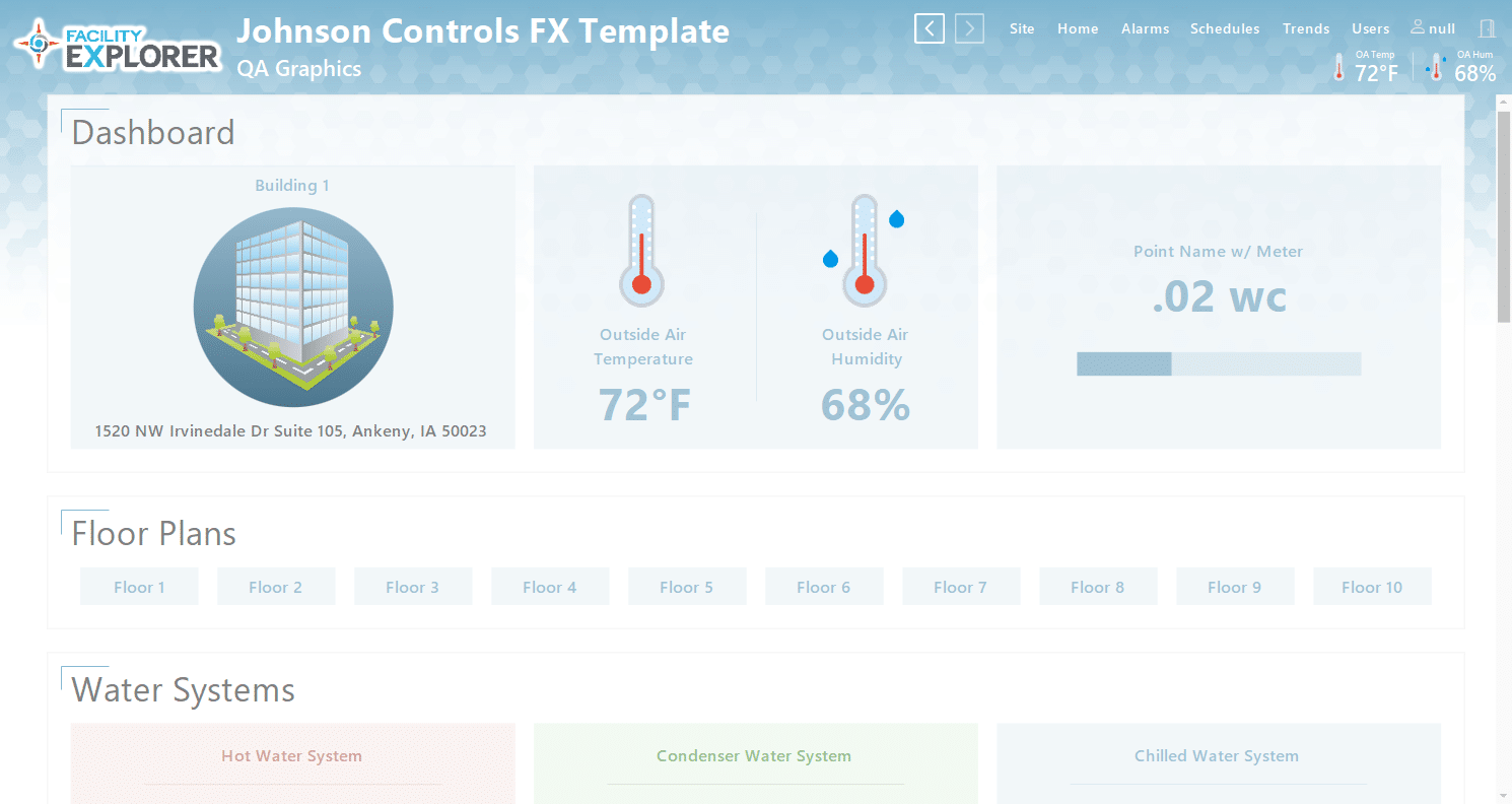
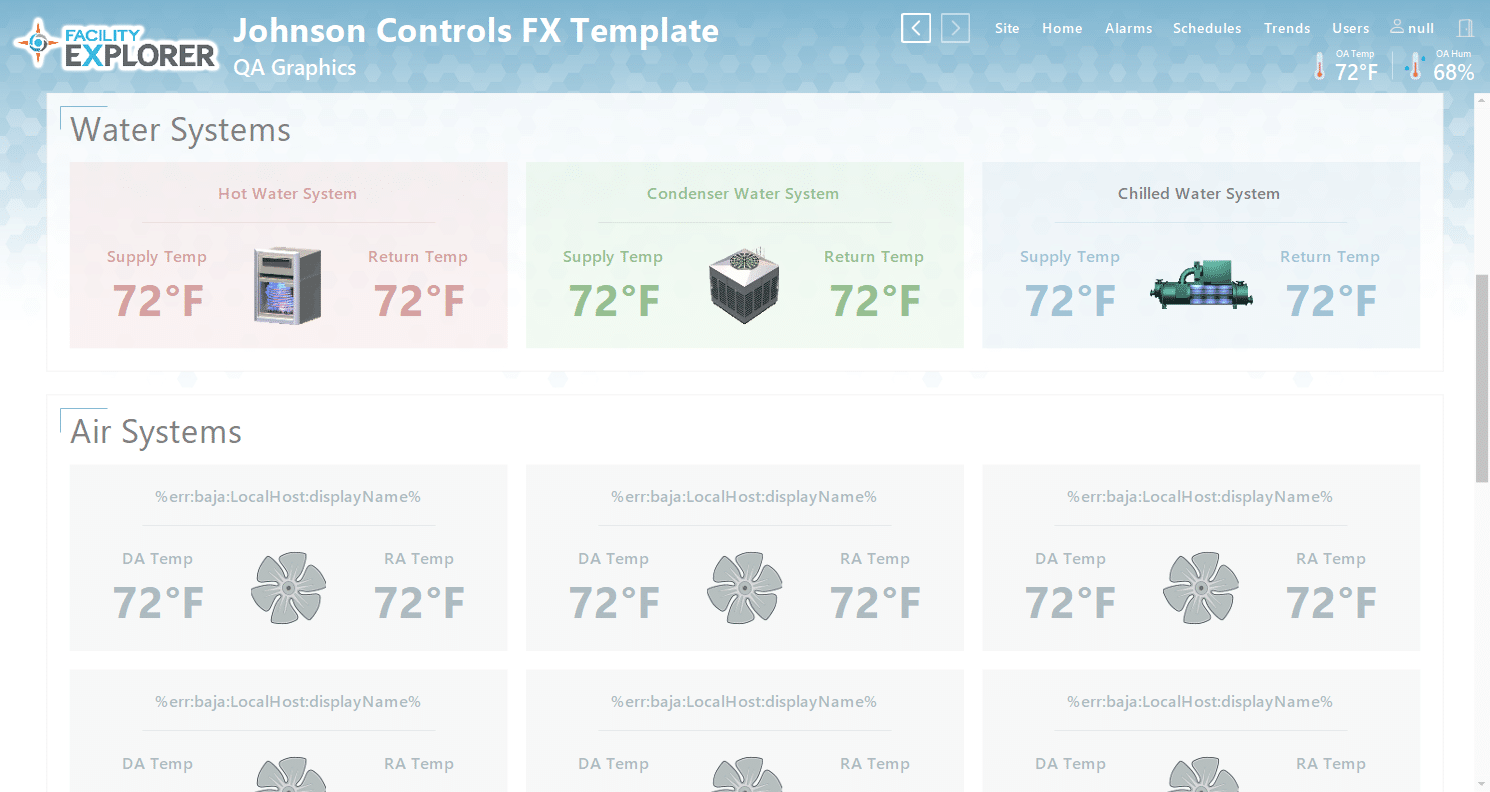
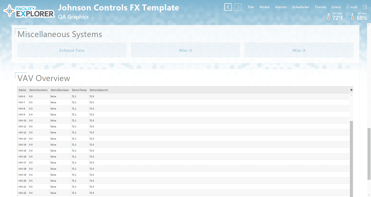
We’re confident in the quality and impact of our graphics, and we’ve gone a step further by developing an enhanced set of templates specifically for Facility Explorer customers. These templates are designed to exceed the standard software offerings—providing greater flexibility, a more polished appearance, and added value from day one.
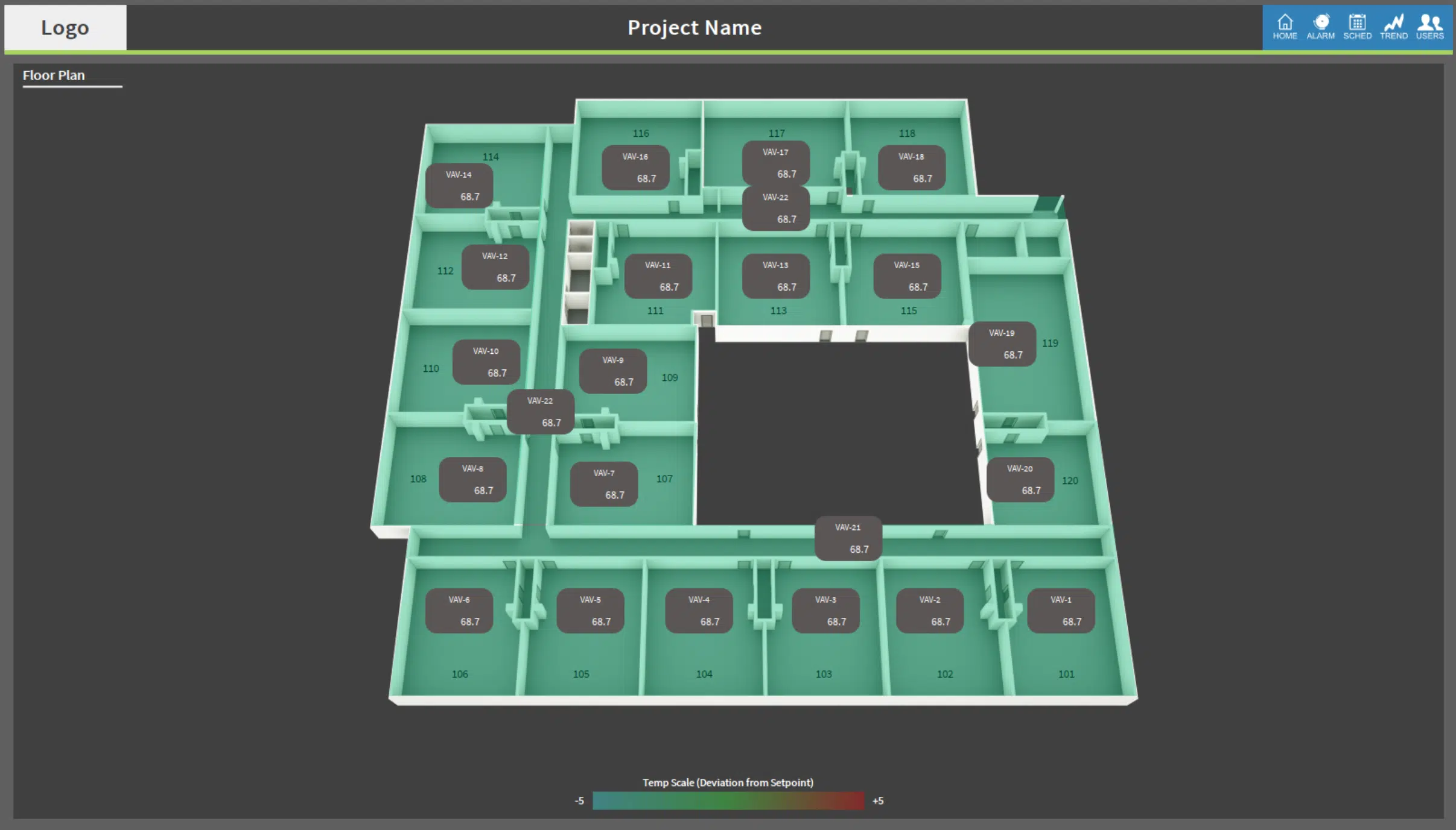
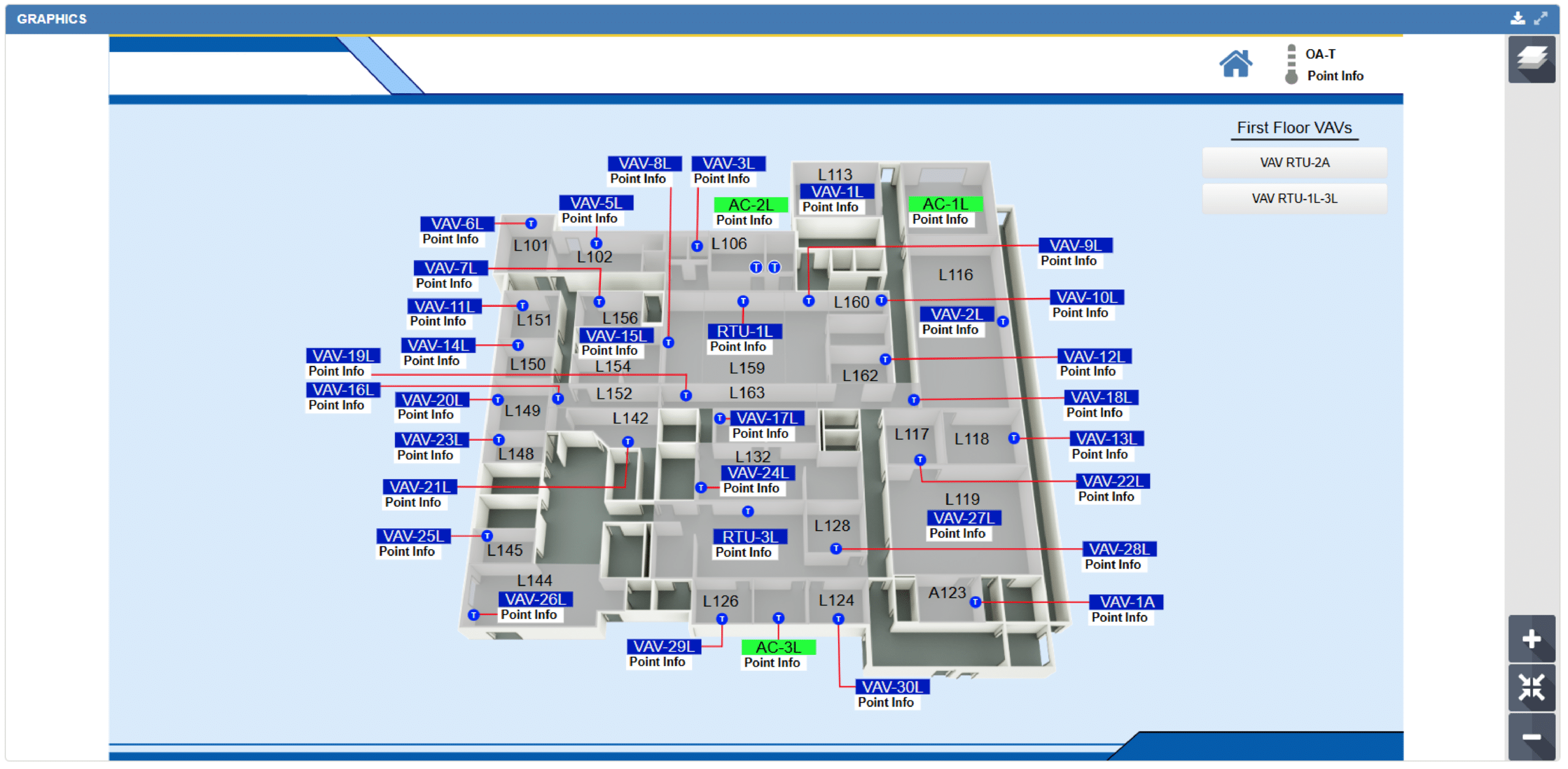
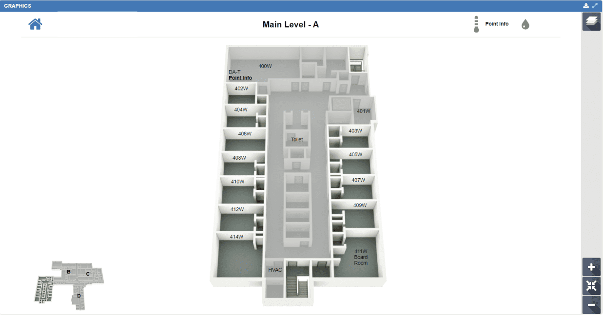
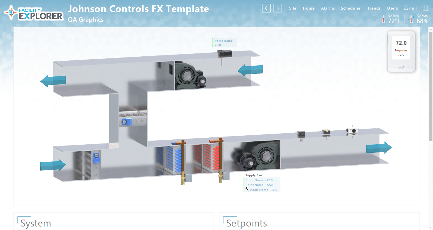
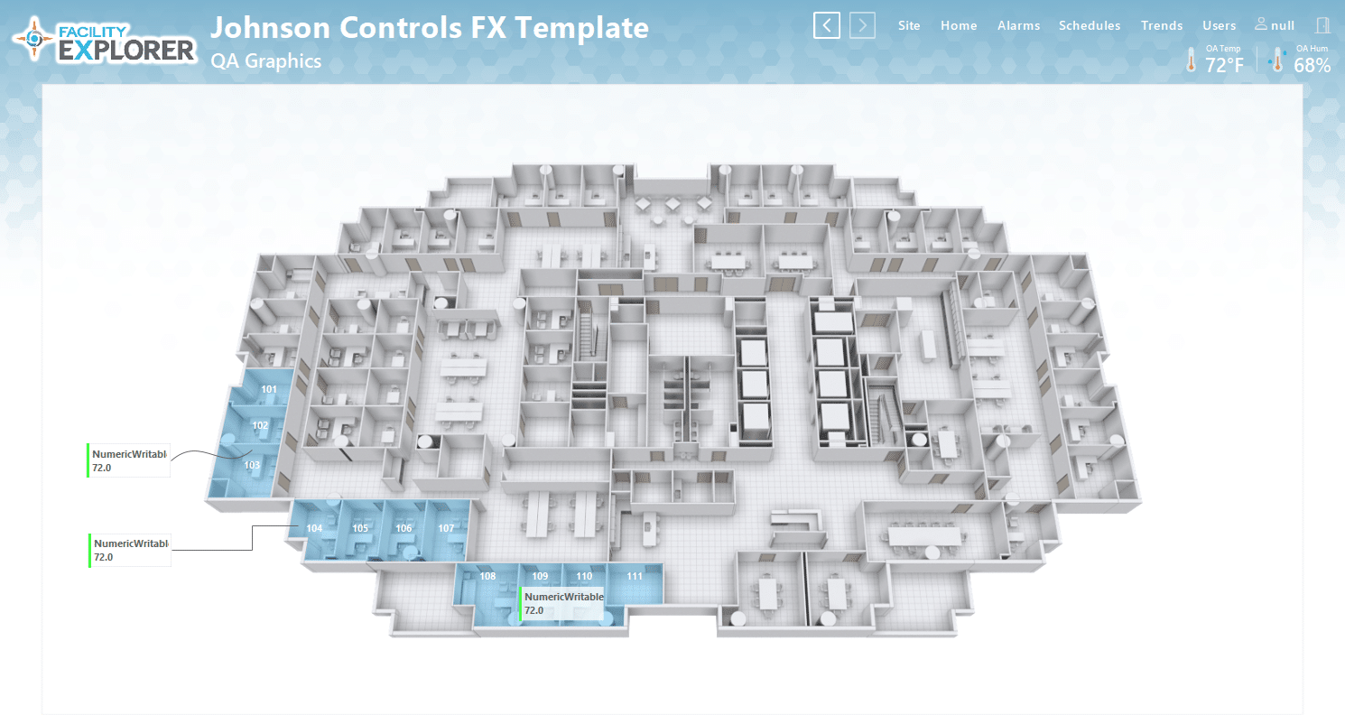
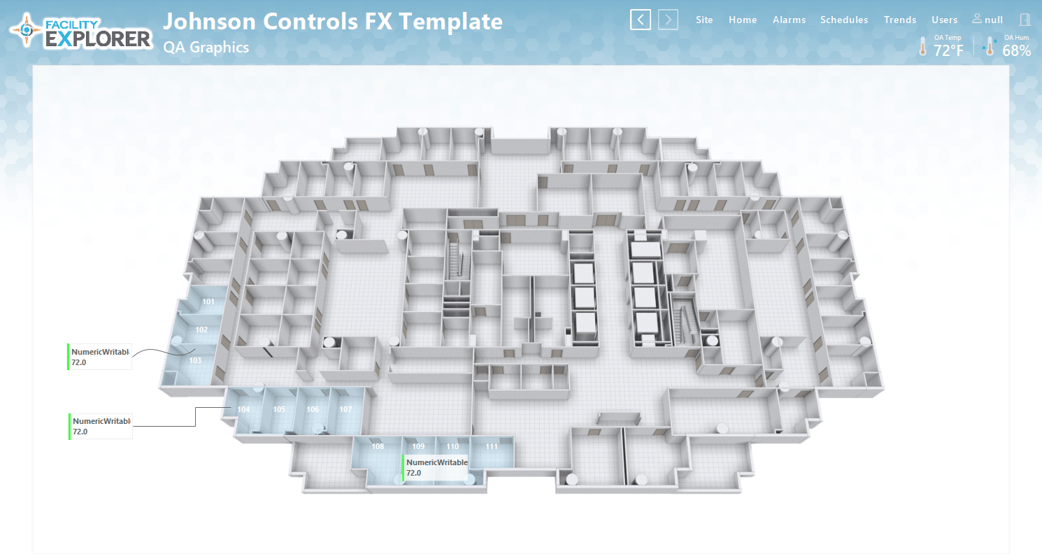
With deep expertise in FX–Facility Explorer graphics, our customized template approach delivers more than just a new look. Each design is carefully structured to create a more intuitive, efficient, and optimized user experience. By incorporating Johnson Controls’ latest 3D photorealistic graphics, we ensure a seamless and modern interface that performs consistently across all devices while maintaining familiarity for end users.
From project kickoff through completion, our team delivers consistent, high-quality graphics backed by a structured submittal process. This ensures every solution is tailored to meet specific project requirements and customer expectations.
We also offer a customized Johnson Controls FX template designed to align with a variety of corporate styles, making it easy to enhance your system’s visual appeal. If your needs go beyond pre-designed options, our team can develop fully custom graphics tailored to your brand and application—ensuring your Facility Explorer solution is both distinctive and highly effective.
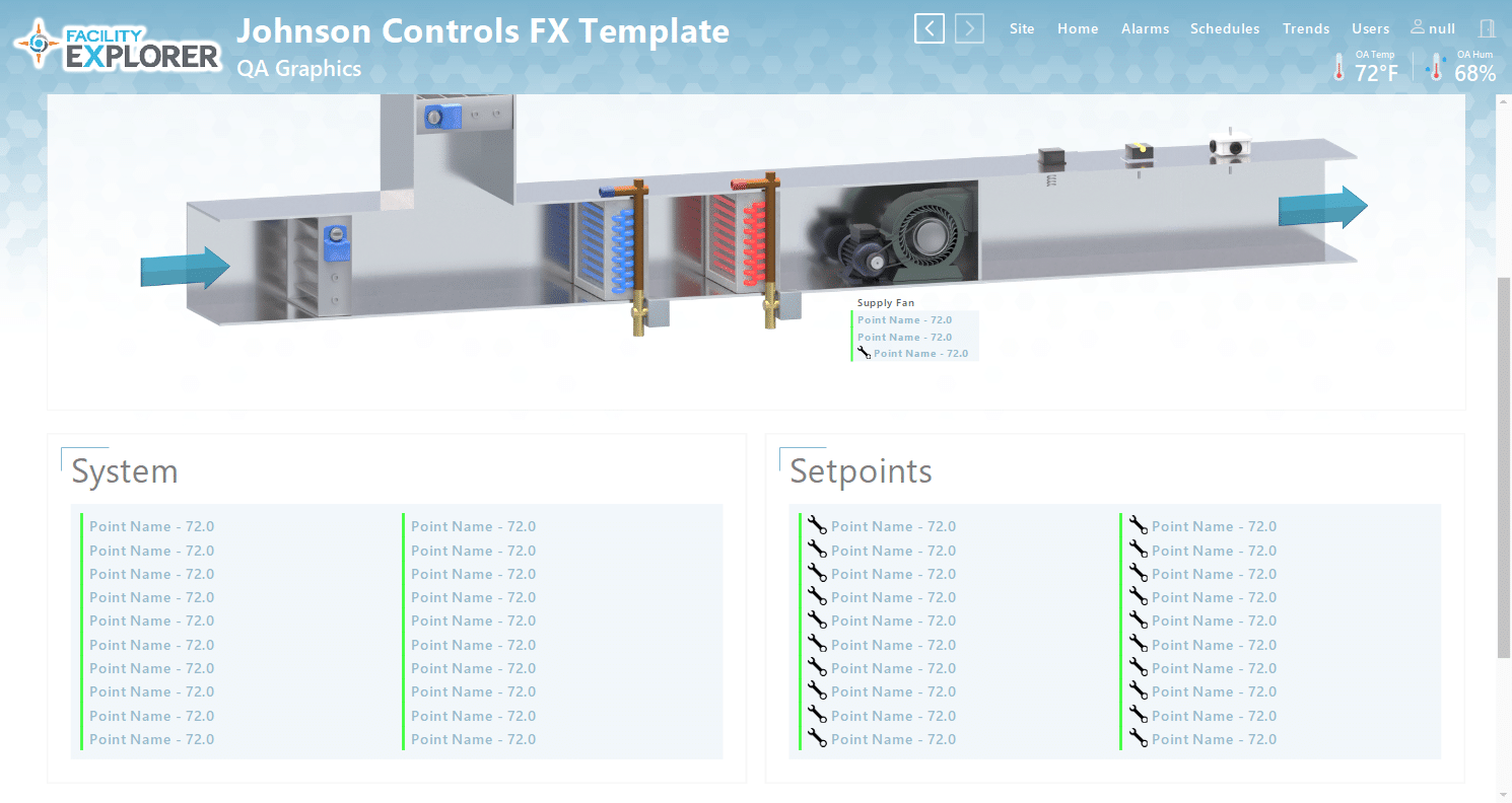
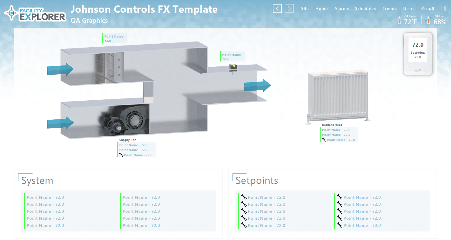
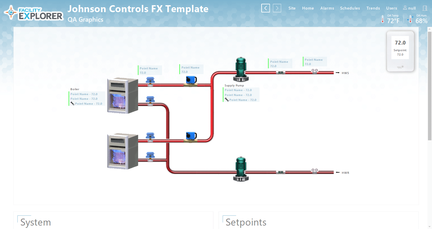
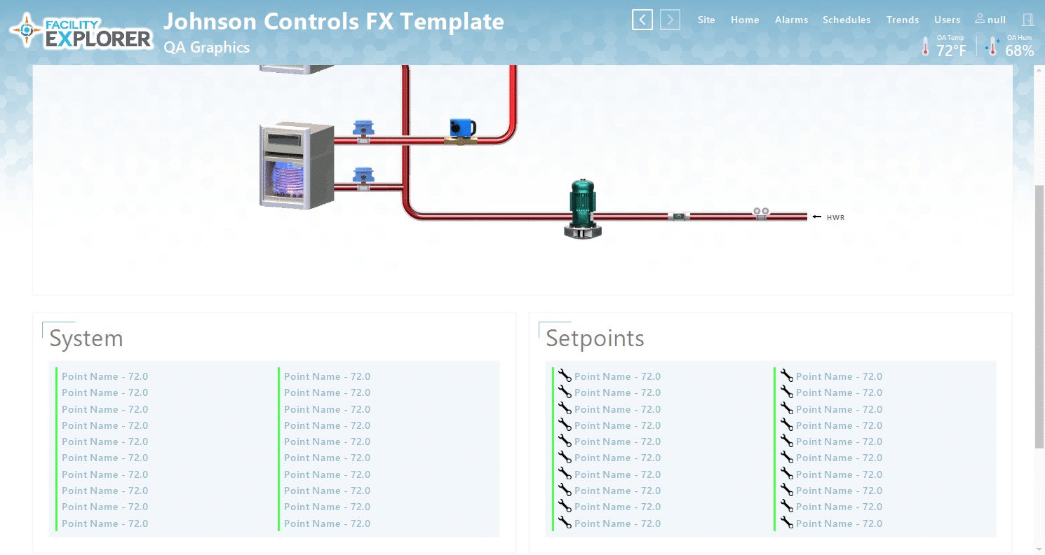
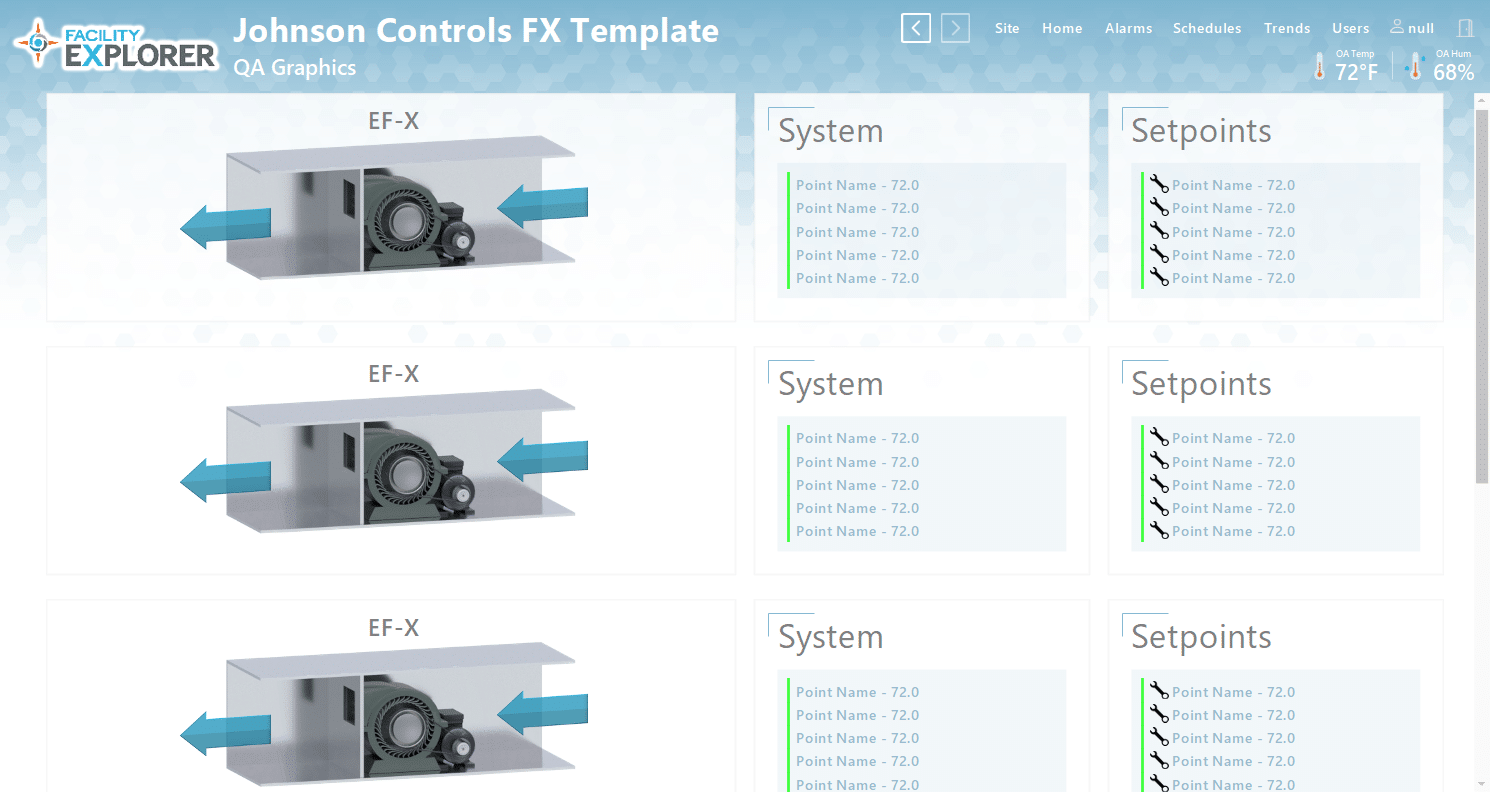
**Please note the graphic examples are displayed using the FX graphics library. QA Graphic’s will be able to use the FX module for those customers who own the library. Otherwise, we can use any inherent Tridium library.
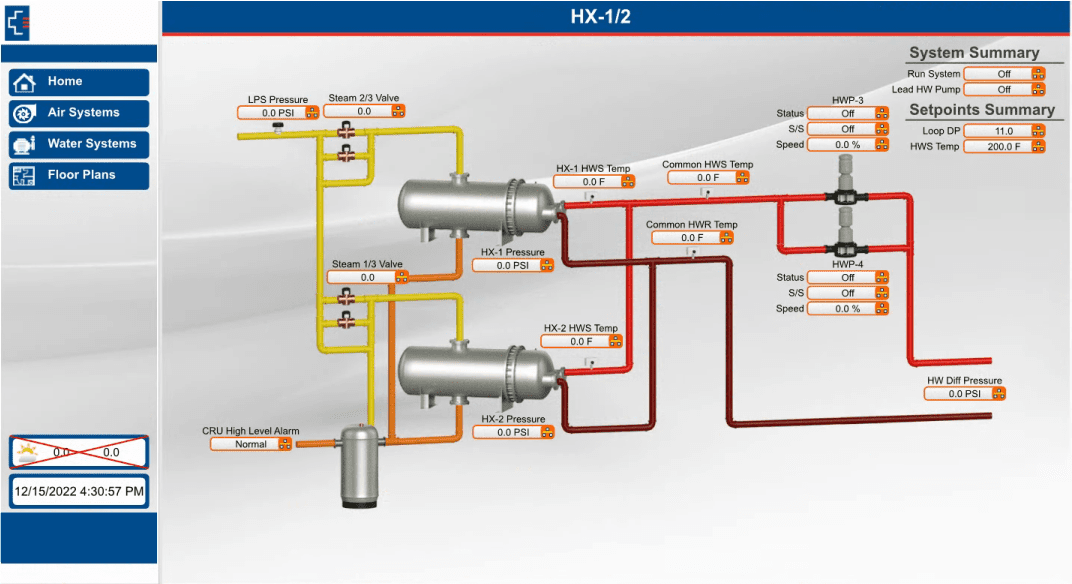
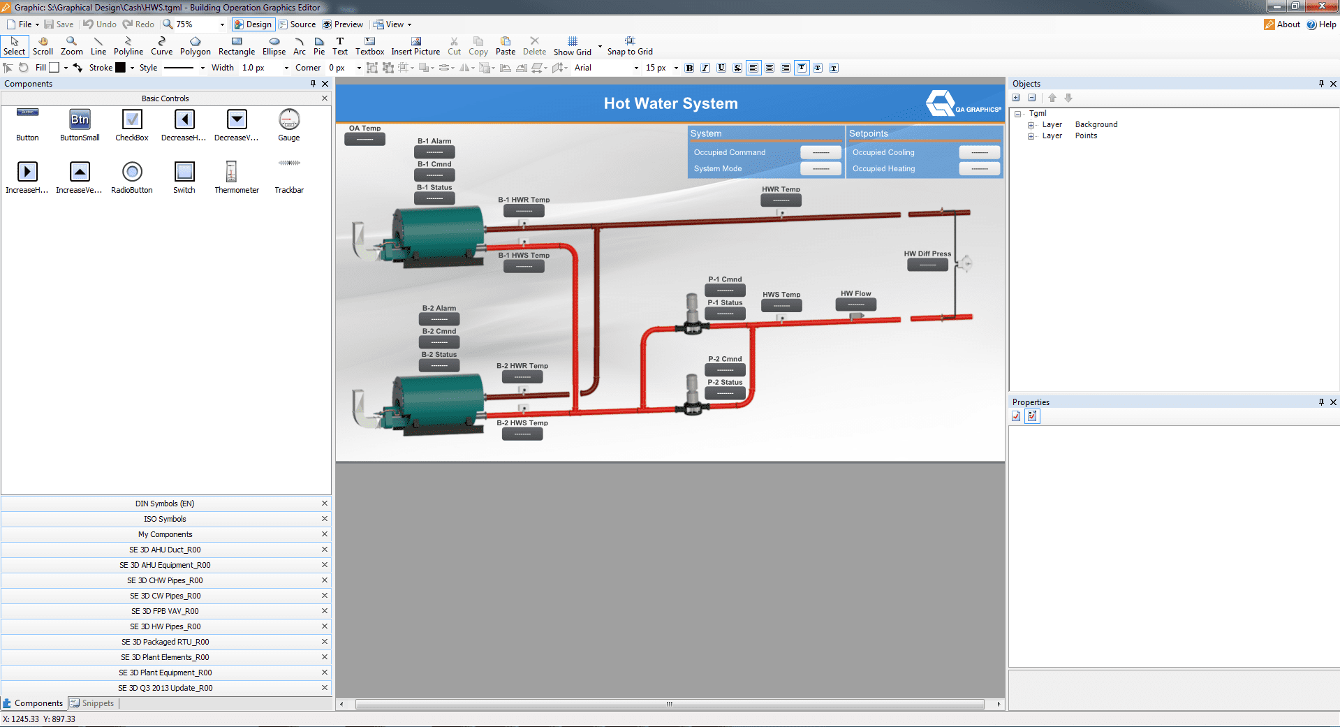
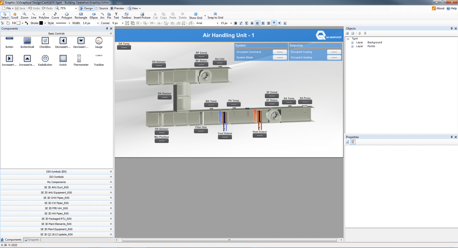
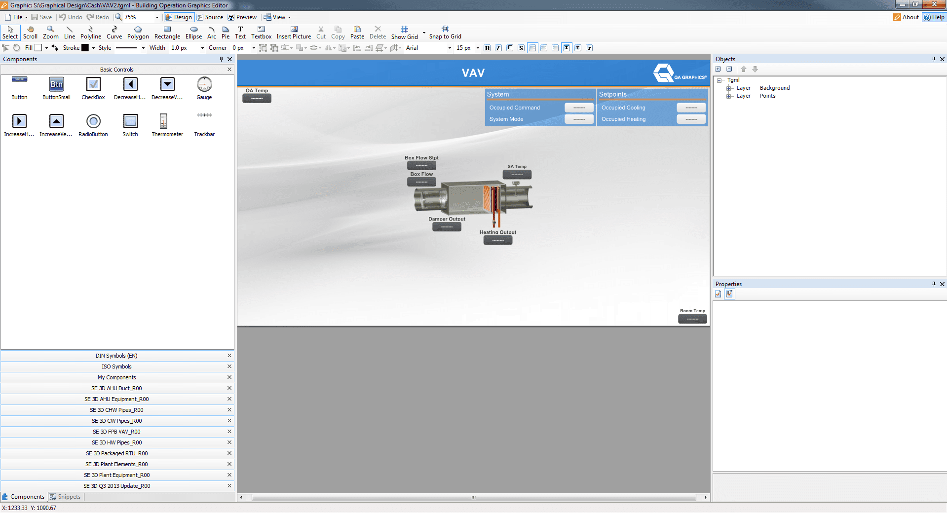
StruxureWare Building Operation
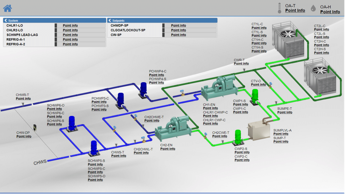
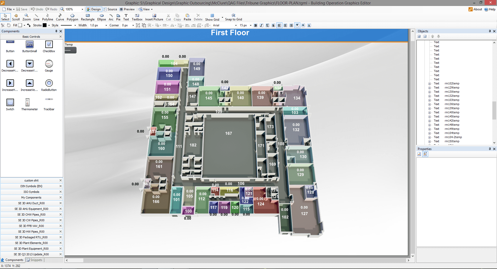
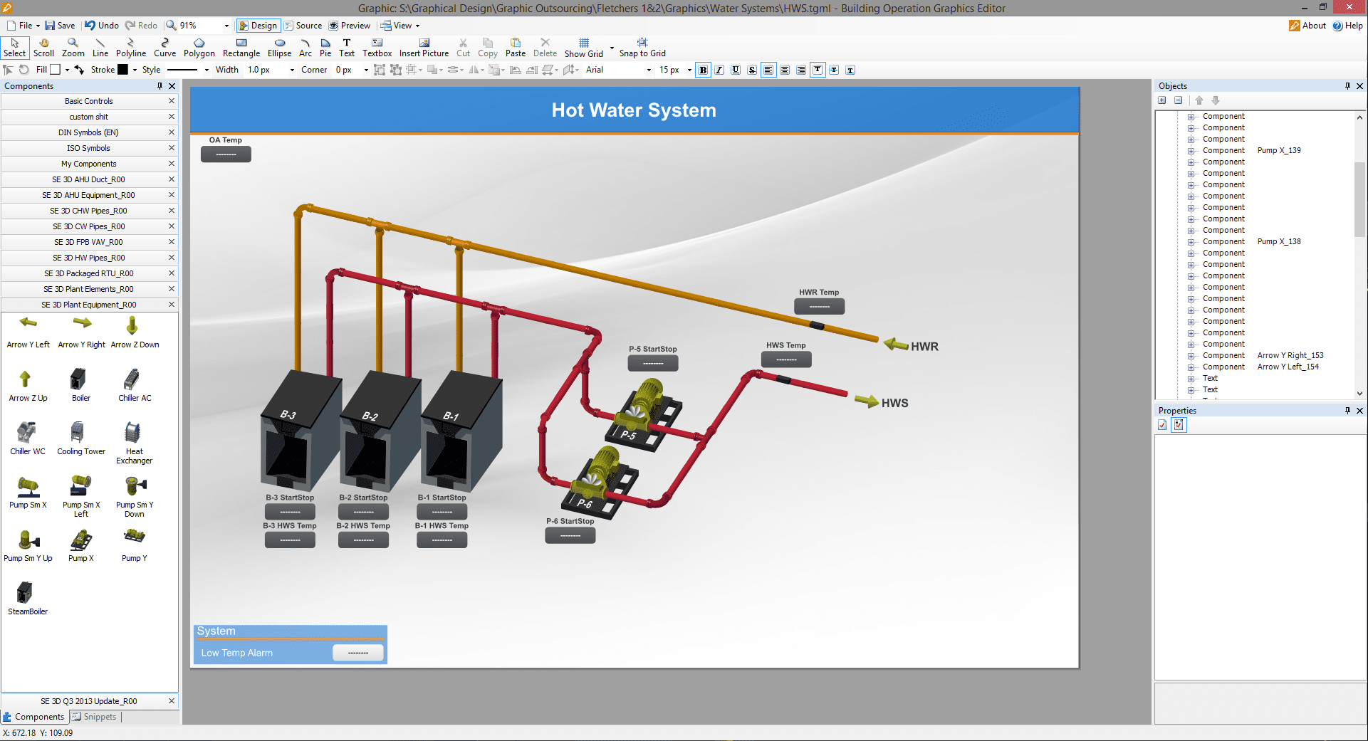
QA Graphics provides system graphics development in the StruxureWare Building Operation Graphics Editor and can implement graphics and bind points in StruxureWare Building Operation Workstation for your project.
We can develop BAS graphics using the existing building automation symbol set or provide custom BAS graphic solutions. We can remotely access your StruxureWare system to install and bind the graphics or build graphics “offline”.
Our team of mechanical engineers and 3D designers are trained and up-to-date with the current version.
We'd Love to Hear from You
We work with clients in a variety of industries. Our trained mechanical graphical staff are the leading developers in BAS (building automation system) graphics for System Integrators, Commercial Real Estate Brokers, and more. We have completed custom BAS graphic libraries for six of the largest control companies in the building automation industry. Learn more about who we work for. Please reach to see if your project would be a good fit.
FAQs
No, we do all our own work in house at our office in Ankeny, IA
Almost all quotes will be turned around within a day.
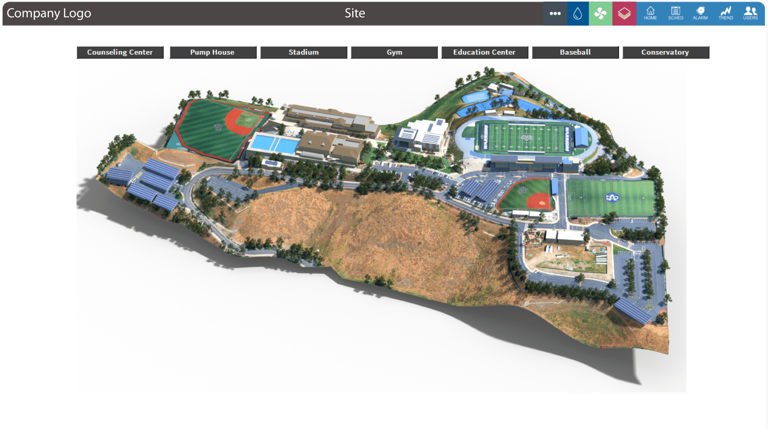
Large campuses may take 2-3 days.
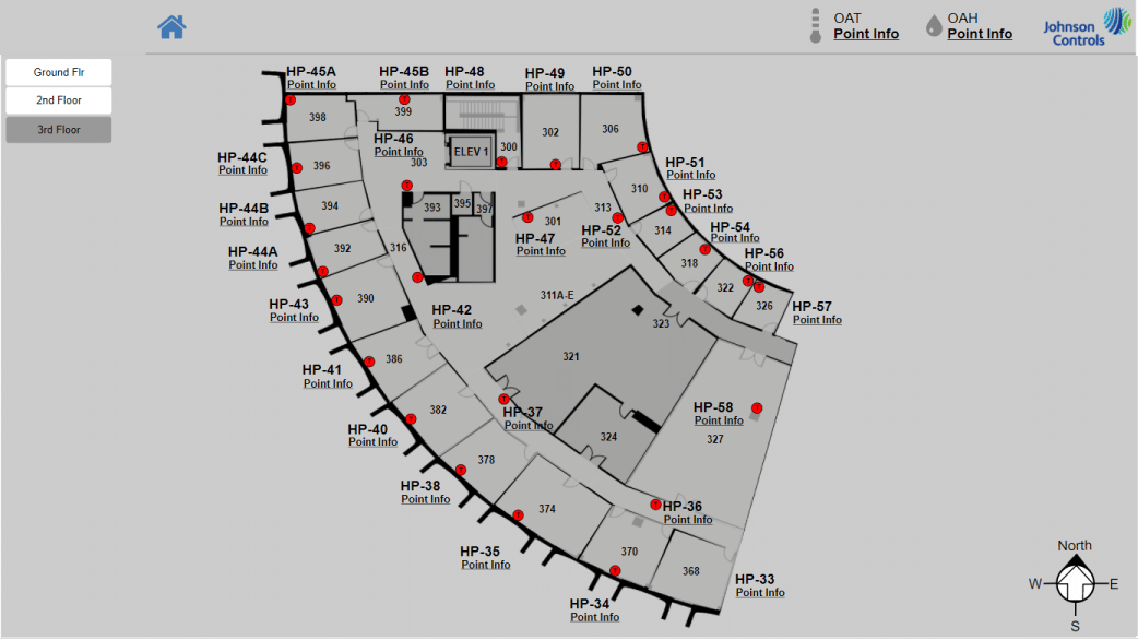
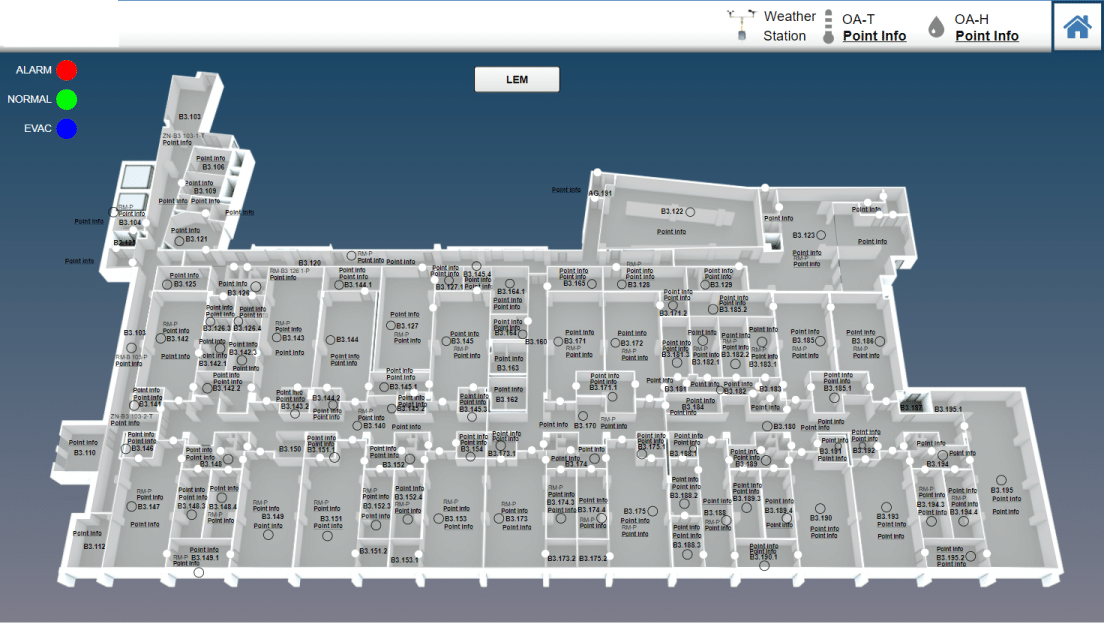
For floor plans: We will require a drawing of the floor(s) for the project and we will need to know what template and package you’re wanting quoted
For 3d Equipment: We will require a PDF submittal of the unit showing both the exterior and interior of the unit. Detailed 3D CAD files (.STEP, .IGES, etc.) can also help result in a more detailed rendering.
For Graphic outsourcing: We will require control drawings and floor plan files or database backup with existing graphics
Once we have the project secured it is turned over to our project manager. The project lives in our project management software. All parties involved are included in the communication throughout the project.
We invoice once the project is awarded, payment is not due until the project is delivered or we have a payment schedule agreed to.
Symbol Libraries and 3D equipment are not delivered until payment has been received.
The acronyms BAS (Building Automation System) and BMS (Building Management System) are often used interchangeably, but they have subtle differences:
- BAS (Building Automation System):
- A BAS refers specifically to the control system that automates and controls various building systems, such as HVAC (Heating, Ventilation, and Air Conditioning), lighting, and sometimes security systems. It focuses on the automation of individual systems within a building to enhance energy efficiency, comfort, and system operation.
- Typically, BAS is more focused on the technical side of controlling and monitoring mechanical and electrical systems.
- BMS (Building Management System):
- A BMS is a broader term that encompasses the monitoring, control, and management of a building’s entire infrastructure. This includes not only the automation of mechanical systems (like in BAS) but also energy management, fire safety, access control, and overall building performance monitoring.
- A BMS often integrates multiple systems, providing an overview of the building’s entire operation, from energy use to security.
In summary, BAS focuses on the automation of specific building systems, while BMS is a more comprehensive system that manages and integrates multiple building functions, including those automated by BAS.
Our Customers

QA Graphics did an exceptional job on the graphics for our recent project, which was full of confusing and complex systems. You would almost think that QA Graphics was part of the project from the beginning. In fact, I have been surprised many times to find that little obscure things were picked up on that I was sure would be missed. I REALLY appreciate the work QA Graphics did on this project.
JAMES PLATANIA
Senior Systems Engineer
– Johnson Controls, Inc –
I would like to throw a huge shout-out to you and your team for all the hard work on the project. After downloading the new MUI package we expected to see problems and were prepared to come back to QA with a bunch of fixes. This was not the case at all. QA really nailed it on this one and we at JCI are so thankful that you are part of the team!! This was by far the smoothest package that we have had to drop in and it really made us look good in front of this customer. This site has now become a showcase piece for future MUI sites and we are excited to show off the work that was done. Again, thanks so much for all the hard work and please let your team know how much we appreciate them going the extra mile to get this done in such a tight time frame. Looking forward to continuing the relationship and growing together as the future brings on more exciting projects.
Brett C.
Account Service Representative
– Johnson Controls, Inc –
Featured BAS Graphics Posts

As AI continues to transform industries, you might wonder why QA Graphics hasn’t fully automated the creation of BAS graphics and 3D floor plans. While AI is a powerful tool, it still falls short when handling the complexity and inconsistency of the assets you provide.

Building automation graphics have evolved dramatically over the past decade. Today’s graphics are no longer simple mechanical diagrams with a [...]

QA Graphics recently interviewed a long-time customer who has been working with us for eight years. The conversation was focused [...]

UI and UX continue to be undervalued in the building automation system (BAS) industry. We are seeing a shift at [...]